
Yes, the cold wx spell persists (currently in the 20’s) so I’m reporting still even more news in the wonderful world of electrical system tasks completed! A lot of what I’m doing is cleanup or finalization from the original install of these components in my panel mockup. Since I’ve used this panel for months now, I am both happy with the design of it and comfortable with the flow. Except for some 1/4″ shifts max –not that I have any planned except the center strut switches– everything is pretty much as it will be in the airplane.
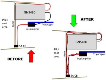
My first order of business today was to solder in 2 lengths of 20 AWG wire (BLACK) for a new GNS480 ground wire(s) run. First, as per my original plan my 2x 20 AWG power (RED) wires run forward from the aft plate of the GNS480 to the front lower LEFT corner of the panel (behind the panel), then from there traverse across the panel just above the leg holes to the 5A circuit breaker in the lower RIGHT corner of the panel. Then one single 16 AWG wire exits the other side of the 5A CB, flows back to midpoint of the panel, then straight forward to the “Deslumpifier,” as depicted below.
After soldering the longer lengths of 20 AWG black ground wire into place, I then labeled the wire as a pair and then ran it from the GNS480 unit to the Deslumpifier, while twisting them with the power wires. The GNS480 power wires are decent sized wires, so I should have thought of this initially when I installed the unit and took steps to mitigate any EMI/EMR noise then. The main reason I soldered in lengths of wire vs just running brand new wires was the terminated ends that I didn’t want to waste, especially the right-angled PIDG FastONs that are a bit pricey. In short, it was just easier and cheaper to solder in a couple of long new wires.
I then targeted the Trio autopilot wiring harness and finished labeling all the unlabeled wires in it. The effort on the Trio autopilot also required me to add about a 6 ft extension of twisted pair of green and orange 22 AWG wires to the existing twisted pair exiting out the harness of the Trio autopilot for connection to the FT-60 Red Cube Fuel Flow transducer in the Hell Hole. Once I cut and twisted (using a cordless drill) the new fuel flow extension wires together, I then soldered spliced them to the end of the fuel flow wires exiting out of the Trio autopilot. I then added a few labels to the entire run of new twisted pair and called that task complete.
I added I would say at least another 30+ wire labels, both in minute recesses of the panel wiring that I had missed, or in the the new wiring schemas I was implementing today. I have to say that, except for a final, no-kidding check on the AG6 warning annunciators, CO meter, and TCW Start Smart module, with all those wires at least ~70% labeled currently, I could install the panel as-is today and be happy with the wire labeling and interconnectivity. What I wouldn’t be happy is with the cable management, which is something I am going to undertake soon to start wrangling all those cables into a nice orderly fashion.
Another puzzle piece I had to figure out was all the OAT probes, specifically the ground points for them. I have one OAT probe connected to the GRT HXr AHRS, one connected to the Mini-X (new design change from the EIS4000), one OAT probe that connects to the HXr but serves as an air/heat duct temperature gauge, and one OAT probe off the MGL clock. I did some research and figured that with the signal voltage on these guys being so low (for example, the MGL uses 30 ga wiring) that I would simply tie all the OAT probe grounds in at one point on the G5 Avionics Ground Bus. I was actually shooting to tie all the OAT probe grounds into the lower, forward G4 Panel Ground Bus, but there’s a specific statement in the GRT manual to keep the OAT probe leads twisted as much as possible to optimize the signal from the sensor. With the G5 bus being higher and farther aft on the Triparagon (i.e. closer to the positive signal wire ports of the respective OAT probes) I chose it as the best grounding point.
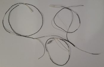
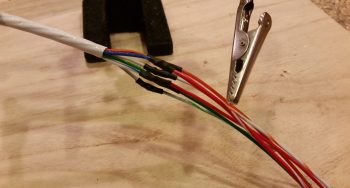
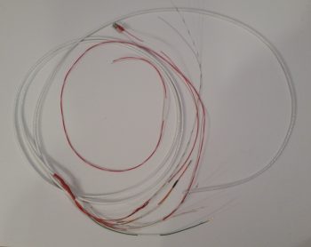
So that’s what I did. Below you can see the 3 GRT OAT probes’ ground leads tied into one lead (lower right corner) ready to be connected to the G5 Avionics Ground Bus. I labeled all the OAT probe wires and terminated the ends to match their respective tie in ports (all D-Sub: AHRS harness, J4A connector, and J3A connector). Since my MGL Clock OAT probe is still on “probation” and subject to being swapped out if it’s numbers (temp accuracy) doesn’t improve, I simply left a pigtail hanging out of the ground harness below to tie in the MGL OAT probe. Once that issue is resolved, I’ll solder in the MGL OAT probe ground wire and heat shrink the splice. [BTW, the GRT OAT probe leads do NOT come twisted… I had to do those by hand so as not to damage the sensors on the end of the leads].
My major push of the day was a 6-wire cable that I bought from Stein to manage and clean up a “myriad” of the single 22 AWG wires heading from in front of the panel to the D-Deck & Hell Hole areas in the back. For a very minimal weight penalty, I now have six 22AWG wires bundled together for their journey aft (or forward…). The 6 “chosen ones” for these wires are as follows:
- Engine data from EIS4000 to HXr & Mini-X
- Serial link from HXr to EIS4000 (for EIS software updates)
- EIS alarm output to AG6 warning annunciator
- Back-up Oil Pressure sensor power/alarm to AG6 warning annunciator
- Hobbs meter power
- “Starter On” alarm to AG6 warning annunciator
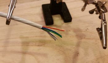
Today my focus would be on the forward (panel) end of this 6-wire consolidation cable. I started by stripping back the outer insulate that then allowed me to strip the ends of the wires for connection to their respective final end-point runs.
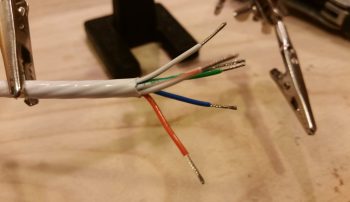
Before I connected the orange wire that provides engine information to the HXr and Mini-X, I soldered in a quick jumper wire that sends the signal from the EIS4000-to-HXr connection (J4 connector) simultaneously through the yellow jumper wire to the Mini-X (J3 connector). Note that I created the 1/4″ bare-wire gap in the orange wire using my wire strippers, then trimmed the overhanging wire off the end when I terminated the wire with a D-Sub socket.
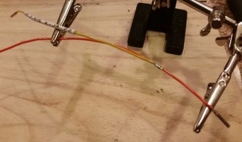
I then soldered the yellow jumper wire to the 1/4″ bare-wire section on the orange wire.
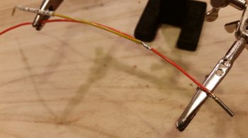
And covered the solder splice with some protective heat shrink.
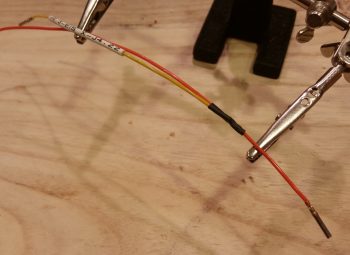
With my initial jumper wire addition task out of the way, I then got busy soldering all the final extension wire runs into place onto the wire ends of the 6-wire cable.
And then covered all the solder splices with protective heat shrink.
I then finished up the extension wire run attachments with another couple pieces of larger red heat shrink.
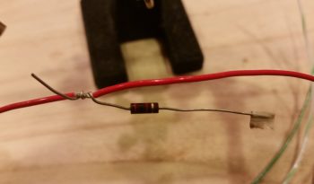
After double-checking my wiring diagrams, I realized I needed another branch off the backup oil pressure sensor’s power lead to drive the AG6 warning annunciator (whenever the backup oil pressure sensor is in an alarm state). However, as per the AG6 manual, this branch run to the AG6 requires an inline 2K Ohm resistor. Ah, and for some reason (wink) I just happen to have some on hand! So I bared yet another segment of wire on the backup oil pressure sensor’s red wire extension run and twisted a leg of the resistor into place.
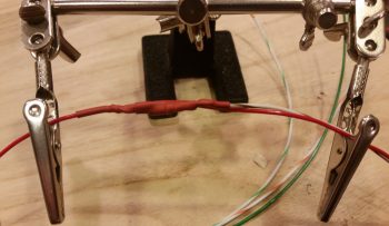
I then soldered both the resistor connection to the backup oil pressure sensor’s red power wire extension run and white/brown lead to the actual AG6 annunciator.

I then covered all that up with some red protective heat shrink.
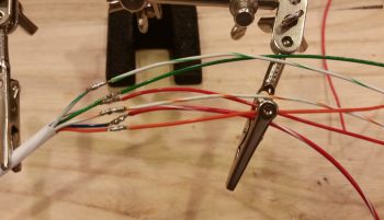
I spent another fair bit of time printing out wire labels and attaching them to the 6-wire consolidation cable front side wire extension runs. I also terminated all the ends of these leads accept the ones headed to the AG6, since those simply get terminated into block terminals on the AG6.
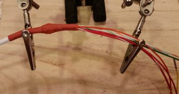
Here’s the half finished 6-wire consolidation cable:
Of course figuring out the front side of the 6-wire consolidation cable meant determining the aft-side interfaces with the EIS4000. During the process of building the cable above, I would fix other issues as I ran across them. For example, now knowing that the panel On/Off LED indicator lights dim and push-to-test functions work, I cut, labeled and terminated the lead that goes from the PTT switch #4 to main bus power.
I also gleaned even more wires from the EIS4000 wiring harness, swapped some GRT wires for better quality Tefzel wires (I’m not a fan of the quality of wires that came on the EIS4000 <specifically> and swapped out 2 of the 3 wires that run into the engine compartment). In addition, I swapped some colors out to better align with the components they were connecting to (say, yellow to yellow, etc.) Finally, I labeled the majority of the wires in the EIS4000 wiring harness. I’ll finish the labeling of a bunch of the EIS and D-Deck/Hell Hole area wires over the next few days.
The last big news of the day is that I spoke with my engine builder this afternoon and the engine build is a go, scheduled for next Tuesday and Wednesday. So, as I mentioned before I will have to curtail my electrical system install shenanigans for a bit and focus on studying and prepping for my engine build.
With that, tomorrow will be another day finishing up a lot of the minutia to-do items on my electrical system tasks list. But, besides the cable management portion, I really do see the panel wiring being pretty much a done deal by the end of the week, that includes design, configuration and labeling. Clearly I’m moving way aft now into the D-Deck/Turtledeck components and am getting that stuff labeled as well as connectors crimped on and pigtails spliced into place, etc. So on my engine info system and Electroair EIS, I’d say I’m near 100% on the design and will be around 75% complete on the actual installs on those two components, with actual cross-component wiring, trans-firewall feeds and mounting the only things left to do after I get the wiring harness leads labeled and terminated.
Movie’ Out!