
Yes, panel build: Day 2.
Today I started off by updating my connector pinout diagrams, reviewing the upcoming connector pinouts and then printing up 2 batches of wiring labels. I had to improvise with some larger yellow wires labels since —surprisingly— I’m out of wire label cartridges.
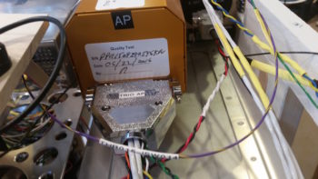
My goal today was to start on the J4A (front side) PQD (Panel Quick Disconnect) connector, but that quickly devolved into working on the prerequisite connector pinout on the Adaptive AHRS for the HXr EFIS. The AHRS is the recipient of a number of wires from the J4A connector, so it was natural to finish this task at this point.
I swapped out a number of wires on the AHRS wiring connector for different colors since some of GRT’s pre-installed wires didn’t match my color coding. I thought about leaving them as is, but it’s a fairly easy task to swap them and will make any future wire-hunting/tracing tasks go much easier if the wires keep the same color on each side of the connectors. I also pulled a few pre-installed wires that I didn’t need. Thus, with the AHRS wiring connector squared away, I installed it and then worked on hooking up the wires coming out of it to points yonder on the panel.
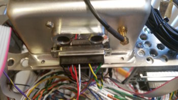 At the aft right corner of the Triparagon… a shot of the PQD connector trio: P6 (currently unpopulated), J3 Mini-X connector (on side, vertical) and J4 HXr (top, horizontal). The relay in the foreground is Relay 9, which handles the COM1 ↔ COM2 swap. I apparently ran out of wire labels after I constructed it, so it took me a good half hour to tone it out and deconstruct what in tarnation I was up to when I made it! And with a 3PDT relay, it took a bit of head scratching. After I got it all figured out and did some quick masking tape labeling, I sent the wires off in their required directions.
[NOTE: This exercise in near-“futility” definitely reinforced to me the importance of wire labels. No matter how in-depth we get into a certain subtask, 6 months down the road all those details are lost –at least to me– and I need to “relearn” what I did! Diagrams and wire labels are the only way for me to pick up where I left off months or years later on these countless wiring components and press forward quickly].
Here’s a closer shot of the PQD bracket and connectors. The front (Triparagon) sides of the J3 (Mini-X) and J4 (HXr) connectors are for the most part complete. There’s another 8-10 wire connections that will need to be added once it’s all actually installed into the aircraft.

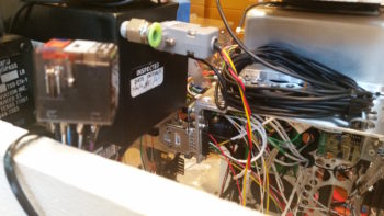
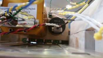
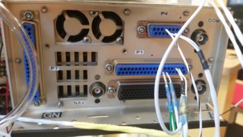
I spent a few hours constructing the 3 x ARINC 429 and 1 x RS232 shielded wire cables that all route through a centralized grommet in the Triparagon from the J4 connector to the GNS480. The pic below shows these cables from the right side of the Triparagon.
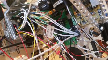
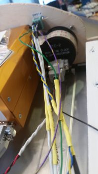
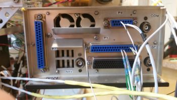
And here are the 4 ARINC 429/RS232 cables on the left side of the Triparagon, ready to be terminated into the GNS480 back plate D-Sub connectors (by the way… I installed the D-Sub connectors on the GNS480 back plate). I only terminated the RS232 cable at this point since it had standard sockets, whereas the other ARINC 429 cables require High Density pins since they get terminated into connector P5 (high density). I’m waiting until I get all the standard D-Sub pins & sockets crimped before I reset my D-Sub crimper for high density crimping.
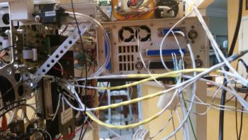
Two of the ARINC 429 and one side of the RS232 connections I highlighted above also feed the Trio Autopilot EFIS/GPS source select switch, the rather diminutive Switch #14. On the right side of the pics above & below, you can see the cross connect cables that are tied into the GNS480’s ARINC 429/RS232 cables (spliced in just before the wires enter the GNS480’s connectors) as they run up over the GNS480 to tie into Switch 14 on the panel.
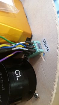
Here’s a shot of Switch 14, the Trio Autopilot EFIS/GPS source select switch, after I terminated the connections by soldering 9 wires to it: 5 connections come from the ARINC 429/RS232 cable group, 3 from the Trio AP control head, and 1 connection from the GRT HXr AHRS GPS signal.
A closeup of the 9 wires connected to the Trio Autopilot EFIS/GPS source select switch (Switch 14).
To get the wire connection lengths dialed in from the Trio autopilot to Switch 14, I had to install the massive D-Sub wiring harness on the back of the Trio autopilot.
Here’s a closer shot of the installed D-Sub connectors on the GNS480 back plate.
 In addition, I also mounted the air deflector on the GNS480 back plate.
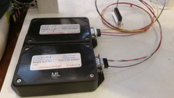
Lastly, I used some of the extra terminated wires that I pulled off the GRT wiring harnesses to make up much shorter harnesses for both the HXr and Mini-X magnetometer connectors.
I suspect that my Aircraft Spruce order should be in the day after tomorrow, so that gives me one more full day to knock out as much as I can on the panel before getting back into the shop. I think I should be close to having the panel pretty much wired after another full day of working on it.