
While at Marco’s I spent well over an hour updating the remaining tweaks I had noted that my panel drawing required to fit properly as on overlay onto the existing composite panel structure. The main areas that are difficult to dial in is the top curve and the leg hole curves, but after a bit I had them as close to what I wanted and was ready to print.
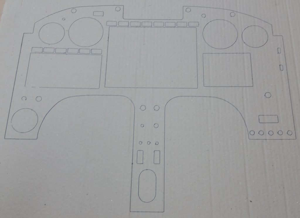
It took a bit more time for Marco to convert the Fusion 360 CAD generated G-code into a usable format for us since we have to have the plasma cutter stop after each drawn component so that we can lift the Sharpie, then position the print (plasma cutting) head to then drop the pen and draw the next component.
Just as before on panel version 1, it was no real difficult feat and after a short bit of time Voila! We had panel version 2’s mockup drawn up on a large piece of cardboard.
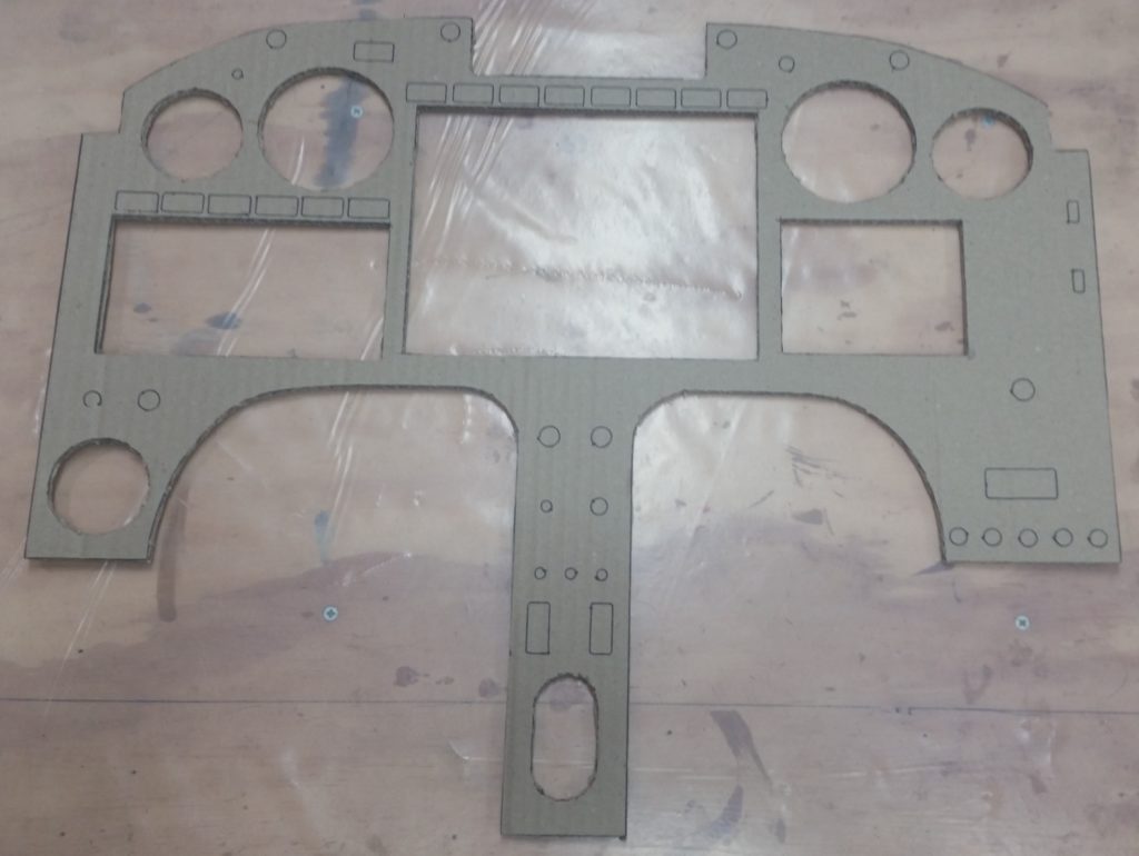
I then spent another half hour cutting out the panel just before me, Marco, Gina, Chris Cleaver and his wife Mary Kay went out for some delicious fish tacos down near the Virginia Beach boardwalk.
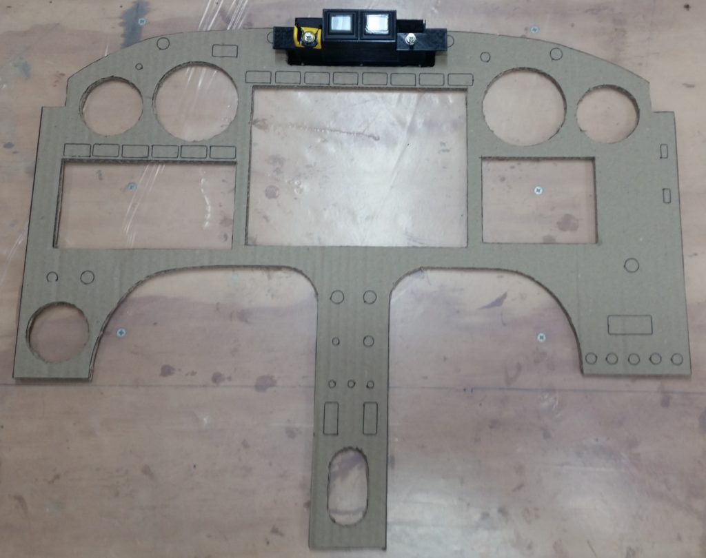
Upon returning back to Marco’s I then set the warning annunciator sub-panel in place in the notch I had created in the upper centerline area of the instrument panel. The fit was good, although I may need to scale down the gap just a touch between the main panel and sub-panel.
I’ll be heading down to the hangar in North Carolina tomorrow, so I’ll be able to do another test fit of the latest version of the panel. Clearly after just another round or two of panel fitting we should have it dialed in nicely and ready to cut the real panel out of 0.090″ thick 6061 aluminum.