
I started off today by finishing up the wiring harness, for lack of a better term, for the MGL RTC-2 clock. I printed out the heat shrink labels, put them on, and then terminated the wires into the connectors (P6 and J4, both B sides).
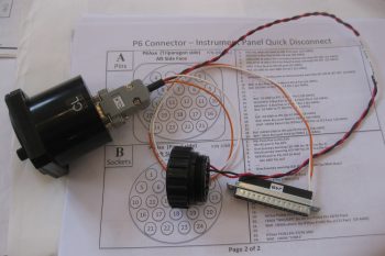
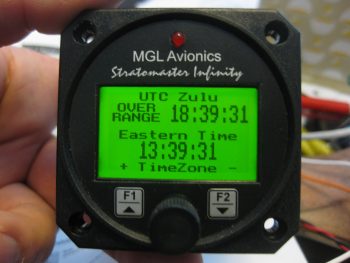
With the wiring finished I then decided to do a quick checkout of the RTC-2 clock, so I hooked it up and fired it up. I then familiarized myself with the screen system and set up some of the parameters. With everything looking good I turned it off, pulled the plug and put it back on the shelf.
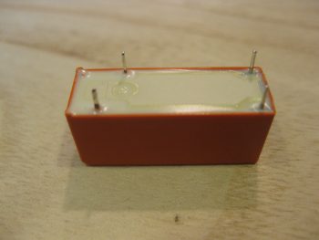
I then started in on wiring up the relay for airspeed switch #2 to control the 3 components that are controlled by this airspeed switch, all below 70 knots:
- Taxi Light extension
- Low speed warning (via AG6)
- RAM air butterfly valve open warning (via AG6)
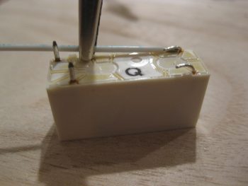
Note in the pic below that I cut off the Normally Open (NO) pin since it’s not required in this configuration.
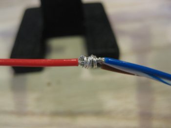
For the power feed side of the relay, off the NC pin, I tied 3 wires into one to connect to the relay. Again, I did the Bob Nuckolls’ technique of using a pigtail from the single wire to wrap around the wire bundle.
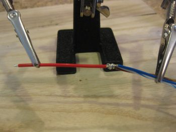
Here’s a closeup.
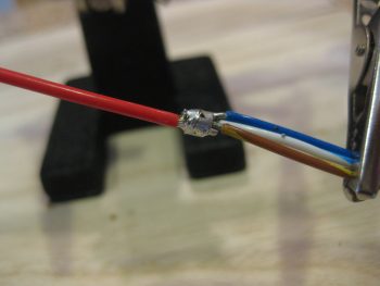
I then soldered the wire connection bundle.
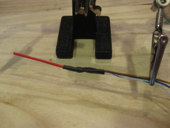
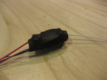
And then covered the joint with some heat shrink for wire security.
 I then soldered the power lead to the relay and wrapped the wires around the relay in prep for heat shrink.
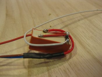
Which I added next. The heat shrink really does a good job of holding the wires securely in place.
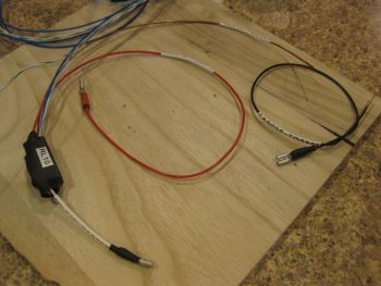
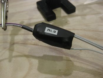
I then terminated and labeled the wires. I also built the separate wire for the #2 terminal on the airspeed switch, which is simply a ground wire to the avionics ground bus (G5) [single black wire in upper right corner].
I then got to work on the last ancillary relay that will be added (at least at this point) to the electrical system: the COM1-COM2 PTT switch relay. Since I only have an (ON)-OFF-ON switch available to me on my control stick, I had to use a relay if I wanted to use that switch to flip between my COM1 and COM2 radios for PTT. Here’s the switch positions:
- ON (Up) – NO relay position that closes to switch PTT to COM2 radio
- OFF (Middle) – Default NC position, keeps PTT on COM1 radio unless flipped up.
- (ON) (Down) – Momentary ON position that is NOT run through the relay. Controls COM1 radio freq FlipFlop (COM2 radio FlipFlop & functions controlled via HXr EFIS). Does not effect the middle OFF/NC relay position.
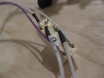
I started with the main bus fed power wire and soldered it to the coil pin.
I then soldered the other wires into place. The purple wire connects to the COM1-COM2 PTT flip switch on the control stick. The 3 wires with the black heat shrink are all 22 AWG shielded wires. The common wire goes to the Dynon Intercom, with the other 2 wires going to the COM1 and COM2 radios, respectively. (COM1 = NC, COM2 = NO)
As with all the other relay packs that I’ve assembled, I then wrapped the wires around the relay and covered it with heat shrink.
I should note that I tested both of these relay circuits out and they both worked great. I won’t be working on the build at all tomorrow (Christmas), but I will be back on it Monday. I would like to also point out that I really am coming to the end of the line on this round of electrical stuff, so I will soon be moving back into the realm of the wheel pants!