I’d like to first off point out that it was a year and 10 days ago (Dec 5, 2015) when I first used the term “Triparagon” in my build blog. Now I of course use it as a common term. And what was once just a flurry of ideas and thoughts regarding the Triparagon has made its way into finalized reality. What the Triparagon has become is even better than what I had envisioned about 13 months ago when I first had the epiphany to do this.
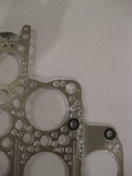
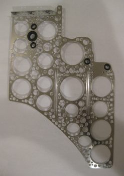
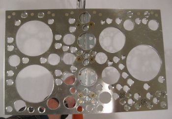
The best plans rarely account for everything, and as far as the Triparagon is concerned I greatly underestimated the time and effort it would take to simply create the lightening holes. Thus, when I looked at the Triparagon this morning, after the “last & final” round of lightening holes, I should have been put in the looney bin when I decided I could go just one more round using a smaller 0.190″ drill bit. So that folks is exactly what I did: an entire FINAL round of lightening holes!
I also noted that I could actually remove a bit more weight by rounding the corners of the vertical Triparagon plate. So before I started in on the final round of 0.190″ lightening holes, I drug out my Saber saw and did some cutting. After I finished rounding off the corners, I then got to work drilling the small holes. If the area could take a 0.190″ hole and still have a good amount of metal for strength, it got drilled!
After the final round of lightening holes was finished, I then set about for the next 3-1/2 hours in chamfering the holes. I did it the in my typically poor man’s milling machine style by using my drill press with a slightly larger bit, and going very slowly (the downward motion, not the bit) to create a nice edge on each hole, albeit a fair number of them are a hair off center.
After chamfering the smaller holes I then finished the edges of the larger holes. [I had to finish up the last handful of smaller holes with a cordless drill since my chuck assembly literally fell out of my drill press while chamfering one of the holes. Luckily the hole wasn’t next to anything important because it created a decent sized crater where a nice lightening hole had once existed!]
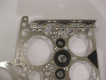
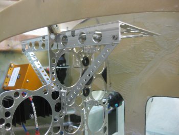
I then drilled and installed 6 larger rivets across the top of the cross shelf mounting brackets to permanently mount them to the Triparagon vertical plate. Afterwards, I drilled 0.190″ lightening holes in-between the rivets.
Then, for the first time, I officially mounted the cross shelf to the Triparagon vertical plate!
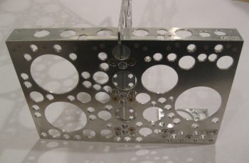
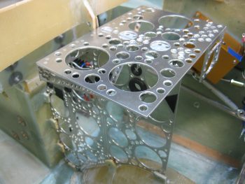
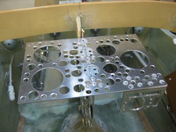
Here’s a top view of the cross shelf. You can see the lightening holes of the cross shelf mounting brackets through the lightening holes in the cross shelf.
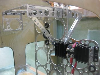
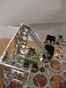
And another view of the cross shelf, after I installed the diagonal support arms (which again requires mounting the Schottky diode heat shrink).
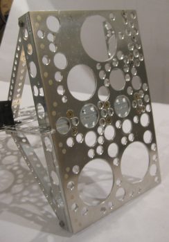
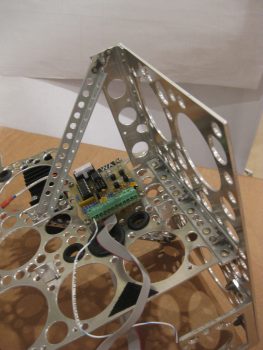
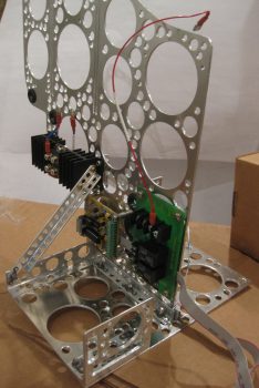
Here’s a side view of the finished & assembled Triparagon structure.
I then took it down to the shop for one final test fit (and the requisite round of pics!) before remounting all the electrical components back onto it. I figure it will be a long time before the bare Triparagon structure sees the light of day again.
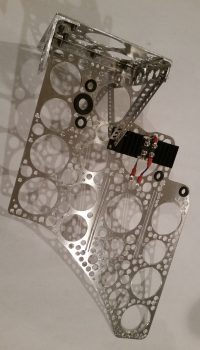
Here’s a shot primarily showing the diagonal support arms and the front cross shelf overhangs.
And from the right…
Here’s a shot from the aft side of the now permanently (but removable!) cross shelf attached the vertical Triparagon plate.
I removed the Triparagon from the fuselage avionics area and took it back upstairs to start reattaching the electrical components to the structure.
Besides the required Schottky diode heat sink, the next items to get attached were the back-to-back attached AG6 warning annunciators (AG6A & AG6B).
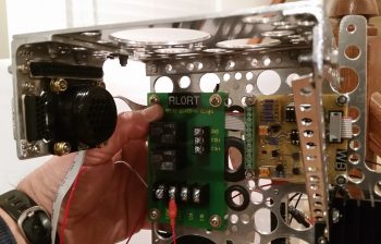
I then remounted the Roll Trim relay board.
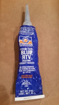
Now, I wanted to use some type of thread locker but all I had was red & blue. I went out on a quick quest to find some purple Loctite, for small diameter screws, but as per usual it was a lesson in futility after visiting 3 different stores. I remembered reading a forum post regarding thread locker from our friends in the VANs world. Sure enough I found it. A guy on the forum reported success with grey silicone RTV, and recounting in my mind the characteristics of the blue RTV I had used (not wisely!) to protect the bolt threads of my canard mounting tabs when I glassed the shear web, I figured I would use that vs. an actual thread locker (second pic below). To be clear, I only used it where I wasn’t using a nut on the other side of the plate to secure a screw.
 I then remounted the 4-port USB hub with locking screws & nuts, and then the Avionics ground bus (G5) and Carbon Monoxide detector (CO), both with blue RTV.
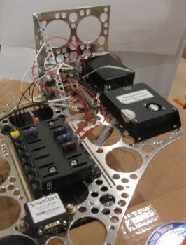
I then remounted the Main Bus and E-Bus, which share the top 2 screws & AN3 nuts, and thus are physically clamped onto the Triparagon plate. The bottom screws for the E-Bus got blue RTV. Only one bottom screw for the Main Bus got blue RTV because the other one is shared as the aft mounting point for the SmartStart module, so it too gets an AN3 nut. Below you can see the E-Bus and the SmartStart module mounted on the left side of the Triparagon.
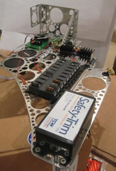
And here’s the right side of the Triparagon, with the Main Bus remounted. I also remounted the Trim relay box (TCW’s Safety-Trim) which shares its aft upper screw as the forward mounting point for the SmartStart module on the opposite side. The other 3 stainless steel countersunk screws on the Safety-Trim box got slathered up with blue RTV.
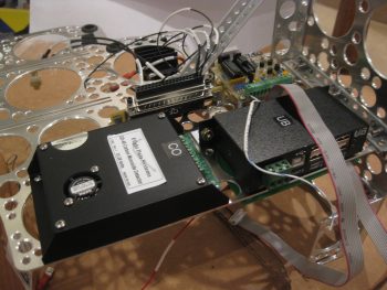
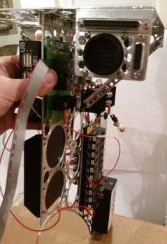
I then remounted the PQD connectors: 1 AMP CPC connector and 2 D-Sub connectors.
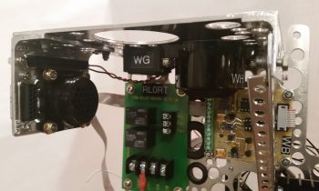
Here’s a shot of the aft side of the remounted PQD connectors. Notice how bare the area is just to the right of the PQD connectors …
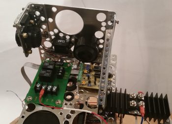
Not anymore! I mounted the gear & canopy warning module (WG) and the Piezo warning horn (WH) in the space just forward of the PQD connectors, on the bottom left side of the cross shelf.
Here’s another shot of the installed gear & canopy warning module (WG) and the Piezo warning horn (WH).
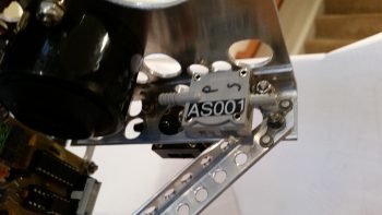
I then got to work on doing a final mount of my 3 airspeed switches. Airspeed switch #2 and #3 were fairly EZ, but #1 was a bit of a pain. I had to remove and trim down the top of the horizontal arm piece on the left diagonal support to allow clearance for the airspeed switch. Specifically clearance for one of the FastOn connectors that mount on the underside of the airspeed switch, which was not accessible with the current configuration of the diagonal support arm.
After trimming the diagonal support arm, I remounted it and test fitted airspeed switch #1. There was still just a bit of interference with the support arm, but I had removed all that I could before actually cutting into a lightening hole. I found a 3/4″ 4-40 spacer and cut it in half, and tried out the 3/8″ spacer (vs the 1/4″ spacer I was already using!). Voila! That did the trick. I then mounted airspeed switch #1 to finish off the mounting of all the “CrackerJack” parts.
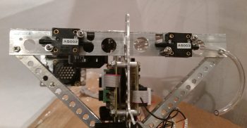
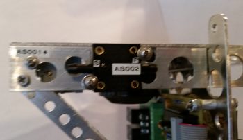
Here’s a closer, albeit blurry, shot of the right-side mounted airspeed switches. You should still be able to make out the airspeed set screw for airspeed switch #1 through the hole in the cross shelf overhang.
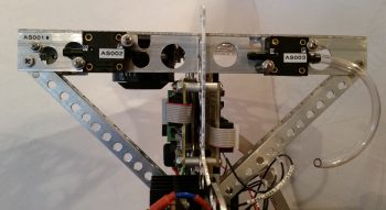
And here’s a shot from behind, showing the staggered #1 and #2 airspeed switches. Note the clearance between airspeed switch #1 and the top of the diagonal support arm.
The final, no kidding, total weight penalty for installing the Triparagon is right at 1.2 lbs. Of course if you take into account the amount of wire in runs saved, and the myriad of separate mounting hardware, glass and epoxy to mount things on the sidewalls in the avionics area, I’d argue that there’s at least a quarter of a pound there, making the comparative weight penalty more around 3/4 of a pound. The weight comparison also doesn’t take into account the increased ease-of-use for the Triparagon.
Tomorrow I actually need to get some stainless steel hardware that I thought I had on hand to swap out with some of the hardware I used today. With Christmas getting closer I still plan on getting stuff done on the build, but it will be a tad less than normal.

