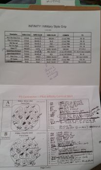
Over the past few days during the Thanksgiving holiday I’ve actually been getting a fair amount of electrical system documentation, planning & system design work done. Some things I’ve done, like taking the time out to figure out the wiring & pinouts for the Infinity pilot control stick buttons, switches & wires, is pretty much a known quantity and simply needed to be completed & checked off the to-do list.
But the pitot-static was a different animal entirely. I had some pieces parts on hand, but I really needed to get educated on pitot-static systems before starting out. During my research I ran across a very nicely detailed post on the VAF forum from Paul Dye (editor of KitPlanes mag) concerning his pitot-static system. In the post he not only described his pitot-static system, and the advice that Stein (from SteinAir) –who we know is a genius on all things panel related– gave him, but how he also devised his pitot-static system, and in turn his electrical system, to allow for the panel to be removed EZily. Hmmm?!
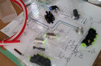
I played around with designing my pitot-static system with the intent to get it documented in PowerPoint and on paper, but have not gotten around to either yet. Although I pretty much have the pitot-static system designed in chicken-scratch form & in my head, as you can see below (the diagram below was summarily stolen from a guy asking questions on his p-s system that posted it to VAF…I’m merely modifying it to suit my needs!). But the panel removal idea –one that Marco and I have discussed non-specifically many times– began to gnaw at me more & more each passing day over these past few days. It was definitely germinating in my brain. One overriding reason is that if I could pull it off, it could literally change the structure & process of how I build the nose of my plane.
So today I spent the entire day taking inventory and listing out every single wire that comes off the panel mounted avionics, instruments, warning lights, buttons, switches, etc. I determined what connectors would need to stay connected, and which ones must be disconnected for the panel to be removed. I created a whole new series of connector designators for the D-Sub and Molex series connectors: J1 – Jn, as compared to the current series of the AMP CPC connector series: P1 – Pn.
After hours of collecting this data, and determining that it could be done, then I got to the business of updating the majority of my electrical diagrams to reflect these new intermediate connectors. I determined a couple of things, at least initially:
- The majority of switches will be on separate sub panels that will be removed from the panel before it is removed.
- The Avidyne P1002 communications connector and the Dynon intercom connectors will have to be removed and stay on the plane side due to the multiple cross/inter- connects to components and the shielded wiring.
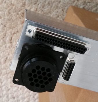
- Given the factors above, I determined the number of pins required could be provided with 37-pin (J4) and 15-pin (J3) D-sub connectors, and utilizing the 19-pin AMP CPC connector (P6) that I had previously planned on using for the GIB stick grip. These should give me enough pins for the panel wiring, with some extra slots. The AMP CPC (P6) and 15-pin D-Sub (J3) will handle primarily power & ground wires, while the 37-pin D-Sub (J4) will handle primarily signal (a ton of RS232) wires.
Of course I need to confirm and refine my plan, but with this in hand and the finalizing of the pitot-static routing plan, I’ll be able to finalize the component placement on the Triparagon, get the top cross shelf and side mounting tabs cut and lightening holes drilled. I’ll also be able to roll these new factors into the design of the top nose structure and see how it effects the forward canopy skirt. Tomorrow will be a light build day, but I do plan on getting a few hours more done on this stuff.


