
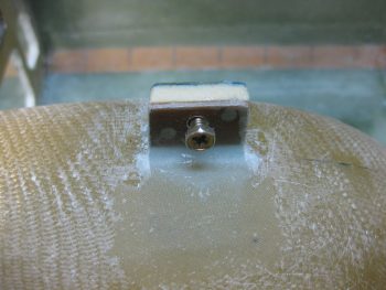
I started out today by trimming the reglassed aft lower Triparagon nutplate mounting tab with the Fein saw. I then cleaned it up by sanding down the edges and then redrilled the hole to allow me to thread in the mounting bolt, which as you can see I’ve done below.
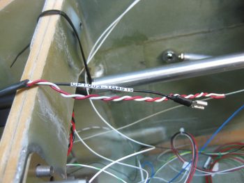
I then labeled the power wires coming off my Atkinson pitch trim servo motor with heat shrink labels on both ends of the wire. As you can see I had to unravel the twisted wire then retwist them back together after the labels were on. However, since the servo motor came from the supplier with these wires, I wanted to test them to see how they held up under heat & fire. I snipped a test piece off and tried to burn it with a lighter for a good couple of minutes to no avail. With my impromptu wire fire rating test complete, I then went ahead and affixed the labels and retwisted the wires.
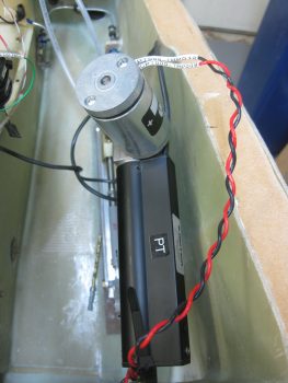
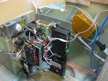
With all my mounting tabs good at this point, I then brought the Triparagon down to the shop and officially mounted it! Here’s a shot of the right side Triparagon. Note the 2 white wires circling around to the right side of the pic and laying atop the Trio A/P pitch trim servo are the 2 Autotrim wires that interface with the servo.
A shot of the right side Triparagon. Again, after all the wires are in place I’ll do some major cable management on this rats nest before it flies.
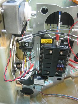
Here’s the left side Triparagon. As I mentioned before, I’m extremely pleased with how this turned out. My next task will be to configure & mount the top cross shelf that will primarily hold the GRT GADAHRS, Trig TT22 Transponder and M760REM COM2 Radio. Also attached to the upper level will be 3 airspeed switches, the Gear & Canopy Warning module, the piezo warning buzzer, and possibly some pitot/static manifold blocks. All these components I just mentioned above make up virtually the entire electrical system other than those components that will be mounted on the Instrument panel.
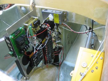
In the pic below of the left side Triparagon, you can see the Voltage Regulator in the upper left of the pic (again, mounted to F22, not Triparagon), the Endurance Buss (E-Bus/EB), TCW Smart Start module (SM), and the Autotrim components on the forward edge. Note in the middle of the pic you can see the twisted red & black wires coming from the Atkinson pitch trim servo motor, terminated with small FastOn connectors to mount on the Autotrim relay (RP) tabs.
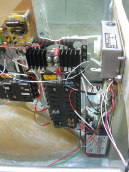
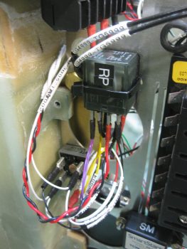
Here is a close up view of the Trio A/P Autotrim components: a bridge rectifier (AT) and a DPDT relay (RP). Again, these components interface with the TCW Safety Trim box, the Atkinson pitch trim servo, and the Trio A/P pitch servo for the autotrim feature to operate.
You may note some chicken scratching writing on the wire labels (…at least you do now!). When I added the Triparagon as a Component Wire Location Identifier [N=nose, I=Instrument Panel, H=Hellhole, etc.] I not only changed these wire labels from A (Avionics Bay) to T (Triparagon), but also the end component 2-letter designator on a few items, including both of these autotrim components. Since this wire label heat shrink is not exactly inexpensive, I made the decision to choose function over form here in an attempt to be both cost effective & pragmatic. Especially on wire labels that honestly are rarely going to see the light of day once this plane is flying. To put this in perspective, I’ve already printed almost 100 wire labels and have attached about 2/3rd of those.
One thing I didn’t show in this post was the unraveling and sorting out of the rats nest of nose gear & AEX wires that sat atop the NG30 cover. I had zip tied them up to keep them out of the way while figuring out my rudder/brake pedal placement, and it looked like an unsolvable/untraceable mass of wires. In reality, since I had labeled so many of the wires, after a good 10 min I had it all pretty much figured out and the wires in place, close to their final runs. So, for the nose gear & AEX power, ground & warning signal wires, I heat-shrinked a bunch of the second labels in place, cut the wires close to their final length and crimped connectors onto a number of them as you can see with the AEX ground wire below that will terminate into the Avionics ground buss (G5).
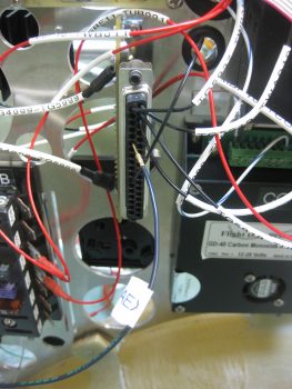 I also went ahead and removed a good portion of the outer sheathing to the 3-wire cable coming from the Atkinson pitch trim servo positioning indicator. The black wire of the group that I labeled and terminated with a FastOn connector will be grounded on the main panel ground buss (G4), while the red & white wires will tie together into one extension wire to feed an input into the GRT HXr to show trim positioning graphically on my EFIS.
I’ll be flying tomorrow, which will of course wipe out a good portion of the build day. Regardless, I’m estimating another 2-3 days to finish up this crazy wiring & Triparagon stuff before I get back onto installing the wheel pants (yes, yes! I know! You’ll believe it when you see it… ha!)