
A good majority of today was all about marking, removing armrest, trimming, sanding, installing armrest, fiddling, marking, removing, sanding, fiddling, repeat, etc. as I spent well over 2 hours dialing in the armrest to accept the cupholder. Of course I didn’t want to go too fast here, so patience was the key. Otherwise fitting the armrest in place around the cupholder would have been a cinch, but I would have had gaping holes at the interfaces.
I also realize this cupholder may stir up some controversy with some of the old guard or pilots viewing it, since it does sit near the front of throttle when in the WOT position. To be certain, I will take measures to safeguard against any inadvertent intrusion into throttle operations by a wayward bottle of soda/water. Not only will the sidewall be marked with “no riders above this height —– ” but I plan to have a little spring loaded swing out arm that not only tells me how tall ANY stowed drink in the cupholder can be, but also secure the container within the cupholder as I do wonderfully fun feats of aerobatics (within limits!) in my EZ.
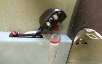
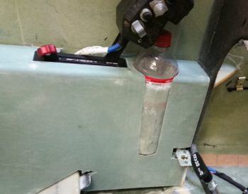
Here’s a closer view of the bottle/throttle interface and the bottom of the cupholder armrest notch. I will layup a couple plies of BID over the cupholder protrusion (taped so it isn’t part of the layup) overlapping onto each side of the notch so that that when it’s painted the armrest will have a nice smooth flow. More importantly, it will secure the very forward part of the armrest, which isn’t held on by much to the rest of the armrest. Btw, if you’re thinking this is a good recipe for pinching some fingers on the throttle, I tried a half dozen times and the bottle top comes nowhere my fingers — so no issue there.
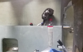
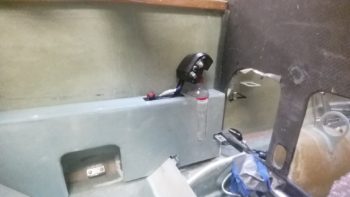
Here are a couple more wider angle shots showing more of the left armrest as well.
I then spent about 45 minutes notching the left side of the thigh support cover plate to clear the protruding cupholder in the left armrest. However, that wasn’t the only clearance issue I had. With the armrest in place I realized I had miscalculated the required width on my thigh support cover plate by about 0.080″ wider than it needed to be if it were to fit comfortably –and be installed/removed easily– while the left armrest was installed. Thus, I ended up sanding a lot of the left edge of the thigh support cover to the point that I removed most of the edge glass down to bare foam. Ahh, such are the pains of a custom design, eh?!
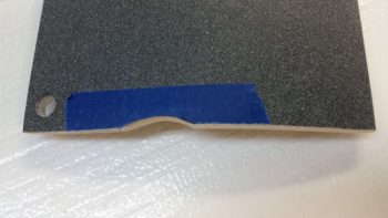
I finally got the thigh support cover to fit in place without it neither protesting as it was installed nor sounding like nails on a chalkboard as the aft left corner scraped down the side of the left armrest! Note the blue tape on the thigh support cover as you can barely see the depression in the side of the installed thigh support (pic below).
I then grabbed a piece of spare “trash” glass and used it as a template that was strong enough to actually keep switches mounted in place. Since this represents the heating switch mounting plate that will replace the front left corner of the left armrest (the armrest front corner foam & glass will get removed), I really only needed the actual shape for the top left side, the left edge, and left half of the cupholder access hole radius.
My primary goal was to see if I could somewhat comfortably get the 2 seat warmer switches stacked one above the other, which I determined I could. And the secondary goal was simply to fit the inboard switches in place… which as you can see I was able to do as well.
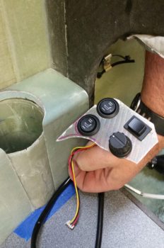
As for the heating switches, I of course stated the outboard switches are the front/PIC & aft/GIB respective seat warmer switches. The dial knob in the lower right is an OFF/speed control connected to the PWM board for control of the oil heat pump. Now, on the HIGH setting each seat warmer pulls about 4.4 amps, for a possible max total of 8.8 amps (On the LOW setting –where I plan to use them mostly– the draw is <1.5A each). The oil heat pump draws up to 7.5 amps. If I combine the totals of just my heating system output, I’m looking at over 16 amps… on a 40 amp alternator! Clearly I cannot allow this to happen, especially in flight. So the upper right button switch is a failsafe that allows me to only use one system at a time, either oil heat pump –OR– seat warmers, not both.
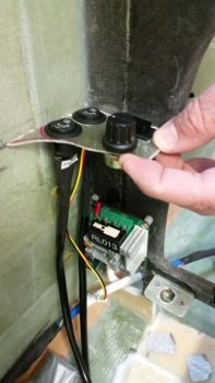
I then checked component installation clearance below the switch mounting plate to get an idea of what all I could fit between the switches and the mounted PWM board, since I had an idea to mount at least one of the automotive relays used to power the seat warmers. Since I need an armrest mounting bracket along the front edge of the armrest, mounted on the lower aft edge of the instrument panel (about where my first knuckle is on my index finger in the pic below), I determined there was simply not enough space for the relay… so it would have to go somewhere else [I had originally planned on mounting 2 relays for both front & aft seat warmers, but then settled for one… then none!].
I then diverged a bit from the wonderful bouts of seemingly endless sanding foam & fiberglass (and itchiness!) to knock out the wiring harness for the heating control system. As I noted above, the pushbutton switch allows me select one system or the other: oil heat OR seat warmers. To do this required me to interject a DPDT relay into the wiring scheme.
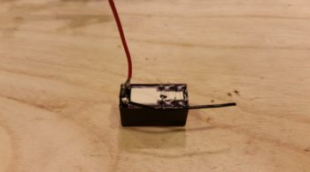
Here are the initial relay coil power wires and flyback diode soldered in place on the heating control switches’ DPDT relay.
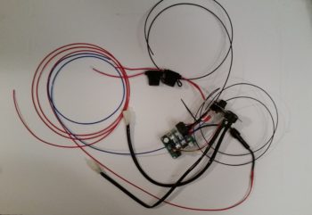
And a couple of hours later here is the wiring “harness” for the heating control system.
To help break it down a bit, the big red wire on the left is the 12V+ power wire that goes from the PWM board to the oil heat pump, via a 10 Amp inline fuse. The big blue wire on the left is the 12V+ power wire that feeds the entire heating control system (either seat warmers –OR– oil heat pump) from the main buss. The big black wire at top is the 12V- GND wire for the entire system that ties into the main GND buss (I ran out of a few colors of 16AWG wire so I didn’t run/connect a GND wire from the PWM board to the oil heat pump). The 2 inline ATC fuses that you see in the middle top area go to the seat warmer relays, one for the front seat warmer and one for the aft seat warmer. The 2 black wires on the right are the GND returns for the seat warmer relays. Finally, the 2 thick black wires at the bottom with terminated Molex connectors are the multi-wire cables to the respective seat warmer switches, front & aft.
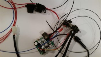
Here’s a closer look at the setup. As a point of physical mounting, I will be zip tying the DPDT switch relay to the PWM board to secure it when the system gets installed.
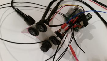
Here’s a final shot of the heating control switches, the PWM board and some of the wiring. I would like to point out that the majority of the wiring for the seat warmers will be replaced with aircraft grade Tefzel wiring.
Tomorrow I will continue my immediate quest to finish the left armrest and all its associated accoutrements.