
Today I started off with the main task of installing a CAMLOC in each corner of the pilot thigh support plate, with an associated mounting tab underneath glassed to the lower instrument panel bulkhead. Well, I quickly realized that to know exactly where the left side CAMLOC mounting was going to reside, I needed to the details of the ELT install. For example: If the ELT couldn’t be set in low enough under the thigh support, then the CAMLOC assembly might sit too low to allow clearance for the ELT and have to be mounted farther inboard. Also, if I did install the CAMLOC mounting tab, that’s just one extra extrusion to bloody my knuckles on as I worked on installing the ELT mounting bracket . . . see where I’m going with this? It’s all sequencing, right?!
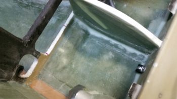
Alas, it was time to work on prepping the lower instrument panel and fuselage floor for the ELT mounting bracket. The ELT is 7.75″ long, so it will extend out from under the seat just a tad, but not enough to get in the way while ingressing and egressing the plane. I also confirmed with the ACK ELT techs that a “few degrees” up or down is not going to affect proper ELT operation. And to be clear: the manual states that left & right should be no more than 10° off centerline, so for up & down I consider anything less than 10° to be ok (the tech didn’t provide an actual value).
I started the process by marking a channel for the ELT mounting bracket.
I then cut the very bottom of the instrument panel bulkhead, that makes up the bottom cross piece of the “map pocket,” which I removed right after I snapped this pic.
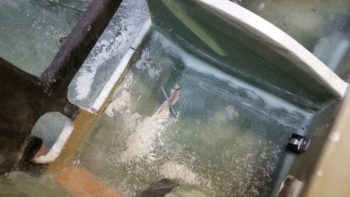
Then, over a few cycles, I trimmed the glass a little and then sanded the channel in the floor down. I kept doing this until I constantly got the angle of the ELT mounting bracket to about 3.5° nose high. I’m definitely going to call that a win.
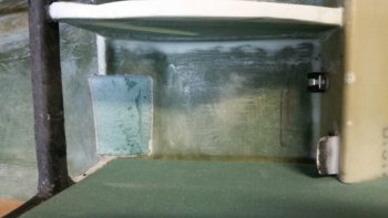
I have a 3″ x 3″ x 7.75″ cardboard mockup that I made of the ELT. I tried that out a number of times during the floor channel excavation. Not one time did I have any clearance issues at the aft end of the thigh support channel. Actually, if you look in these pics the only issue I had was when I was re-leveling the fuselage at the longerons. My electronic level fell into the cockpit and put a nice divot in my front seat, then it slammed into the wedge duct top corner and dinged it up pretty good too.
I need to ponder a little more and assess just how I’m going to install the ELT mounting bracket. I have some ideas, but I wanted to let them germinate a bit before glassing this all up.
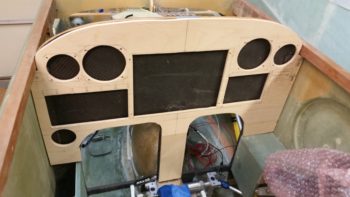
Today I also cut 2 small side pieces and the center strut for the mockup instrument panel. I then glued them in place at the bottom of each panel area (L, C, R) with wood glue. An hour or so later I did a quick mock up in the fuselage to see how the mockup test panel compares to the real one. Looking pretty good!
I also did a number of things with the panel mockup, such as mount it to its base (sorry, no pics… yet). I also installed the GNS480 mounting tube and test fitted the 480… which installed nicely.
I’ll need some mounting brackets for the CAMLOCs to hold the thigh support cover plate in place, so I took my 1″x1″ piece of 4130 steel and taped it to a glassing board. I then covered the top and outer edge with a piece of clear packing tape.
Then I laid up 7 plies of glass: 6 BID and 1 UNI, to make up a 1x1x8″ angled composite mounting bracket… which will of course get cut into 8 little mounting brackets. Once I laid up the glass plies, I of course peel plied the layup.
Tomorrow I have to run some errands and visit some people, so I won’t be back in the shop until the afternoon. But I do plan on setting the nutplates and glassing in the base for the ELT, and possibly getting a couple of 90° mounting brackets made up and ready for installing the CAMLOCs.