
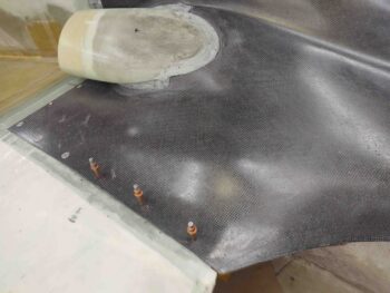
I started out today spending about 30 minutes on each floxed-attached armpit air intake scoop to Dremel down and then sand the edges for a better transition between scoop edge glass and bottom cowl surface.
As you can see, I also re-drilled the pilot holes into the added glass on the wing cowl mounting flanges and re-installed the clecos. Again, with the added plies of BID on the flanges the interfacing levels of wing and cowling surfaces are very acceptable to proceed with micro finishing for paint. I will point out again as well that I’m leaving the aft 2 CAMLOC positions clecoed only until the upper cowling is fitted, mounted and integrated into place with the lower cowling.
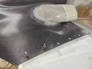
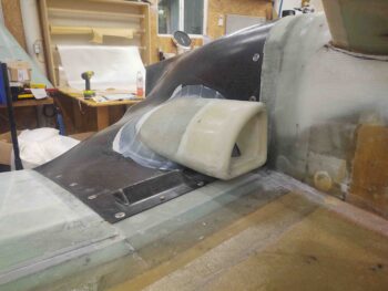
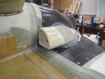
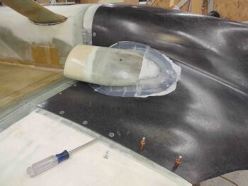
I then proceeded to layup 2 plies of stepped BID around the perimeter edge of the armpit air intake scoops. Along the tops and bottoms of each scoop the first ply of BID was 1.8″ wide, while the second and final ply was 1.1″ wide. On the very aft half-circle shaped part of the scoop the first ply was 2″ wide while the second and final ply was 1.5″ wide. I stepped these plies and made the first a little wider than probably needed just to help with the transition and flow between the scoops and cowling surfaces to better facilitate micro fill finishing.
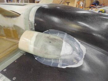
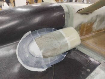
Here are shots of the glassed scoops from the front side.
I left the scoops to cure for a few hours, and with using fast hardener they were well on their way to final cure when I pulled the bottom cowling off the plane. I then pulled the protective tape from the inside edge of the cowling, at the corners.
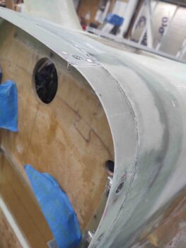
I then checked out the freshly glassed 4-ply BID corner flanges. Not bad at all, especially since these corners have been the problem children of this bottom cowling install!
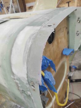
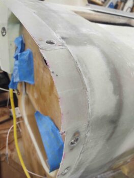
I then trimmed and sanded these newly glassed flanges… again, more than acceptable in how they turned out.
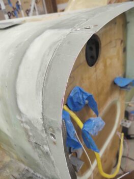
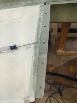
With the added plies of BID in place and wing-to-cowl surface interface levels confirmed, I actually drilled out the hole for the #3 CAMLOC before removing the cowling. I then drilled the flange side hole out one more step to 1/2″. I then installed yet another Skybolt lightweight stainless steel CAMLOC receptacle onto the flange (screwdriver used as pointer).
After pulling all the protective tape and peel ply from the added 4-ply corner flanges, trimming the flanges and then installing the new #3 CAMLOC on the right side, I then reinstalled the bottom cowling to let the armpit air intakes’ securing BID cure with the cowling in its mounted position (just in case).
Note that here we have the #3 CAMLOC on the right side installed. Interestingly, the CAMLOC studs required along the front edge of the cowling are all -3’s. Then along the sides I needed -4’s. However, with the 2 added plies of BID at the #3 position, this CAMLOC stud length needed to be a -5.
Tomorrow I plan to glass 1 ply of BID to the inside edge of the air scoops overlapping onto the inside surface of the bottom cowling. I also plan to mitigate (glass) the small corner air gaps between cowl and strake/fuselage corner. After that, I’ll be cleared hot to start back to work on the hell hole hatch and cover, as well as the RAM air scoop configuration and install.
Nice work. Nailed another tricky series of steps to get those cowls cleanly attached. 😊
Thanks Dave! Inch by inch trying to get this thing done! ;)