
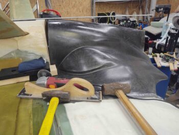
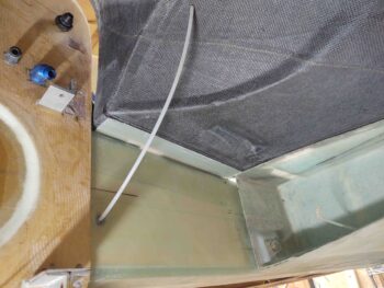
I started out today with setting the bottom cowling in place to get it aligned in what will be its mounting position. My primary focal points for alignment are the inside right angle cowling corners where they intersect at the junction of the strake and fuselage side.
The goal here after I got the cowling aligned along the centerline of the fuselage is to cut the front horizontal cowling edge to interface with the 1.6″ flanges I just glassed onto the aft side of the strake/CS spar. To get a good cut line I had to weigh down the outer corners and along the sides where they meet the inboard bottom edge of the wing.
I initially attempted to use my laser to mark the fuselage, and in turn the cowling, centerline. But with the fuselage and wings NOT at 0° level (I didn’t foresee a need for them all to be level, so I didn’t make the effort to do so… oops) anything below the top surface (as situated… so technically “bottom”) centerline the line started to skew to one side. This drove me into having to go old school and manually determine the centerline.
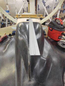
Once the cowling was centered and aligned, checked, rechecked, and double-checked, I then climbed underneath the cowling and marked the cut lines along the aft edge of the 1.6″ flanges coming off the strake/CS spar.
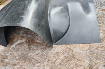
With the cut lines marked, I then removed all the weights off the edges of the cowling and took it outside to cut the front edge horizontal sections. As you can see, I clamped a straight edge just forward of the line . . .
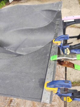
And carefully cut it with my Fein saw.
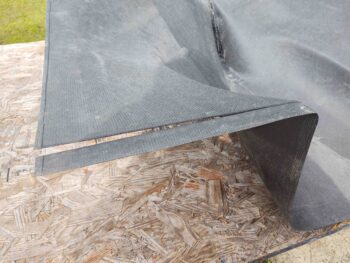
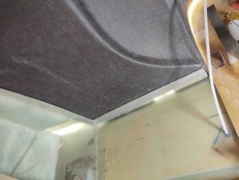
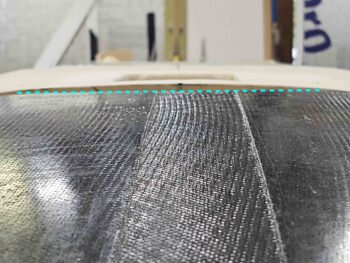
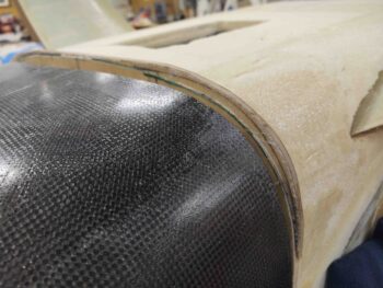
Here’s the trimmed horizontal section on left side.
And the same on the right side.
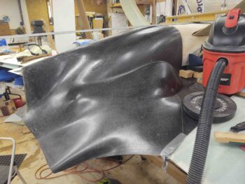
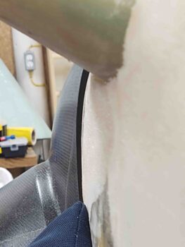
After resetting and realigning the cowling back onto the plane, I then started assessing the interface between cowling and firewall/hell hole/aft bottom fuselage. It was clear right off the bat that the bottom middle of the cowling is somewhat flat and I did not capture that flat edge on the bottom of the firewall. Thus, that required re-cut/trim was added to my task list.
The major alignment issue between the bottom cowling front edge and the aft fuselage/ firewall is on the left side. The first issue is the shape of the cowling itself. The lower “U” section of the cowling, that actually interfaces with the sides and bottom of the firewall is not exactly symmetrically: so instead of a true ∪ shape, it skews towards the left a bit…. so more like a slightly slanted U vs the desired straight U.
I’m not sure if this skewing is a result of the cowling having been in shipping mode and storage for the past 10 years, or if it came off the mold that way. Regardless, it’s not by a huge amount… we’re talking maybe 3/16″. My thought is that by securing the left side with a CAMLOC it will pull the left cowling edge in tight and thus correct the rest of the alignment woes around the perimeter of the firewall.
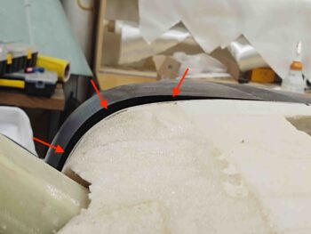
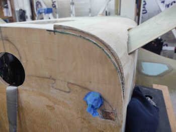
Related to issue #1 is my mismarking of the firewall before I did the “final” trimming of it as I started work on filling in the aft bottom fuselage and hell hole area with pour foam. I somehow managed to remove a fair bit more than I should have in the lower left “corner” of the firewall. The result is a gap, that I’ve highlighted here with the red arrows.
Luckily I saved the cut edge material I removed when I trimmed the firewall. Here I’ve simply set it back in place on the now trimmed firewall.
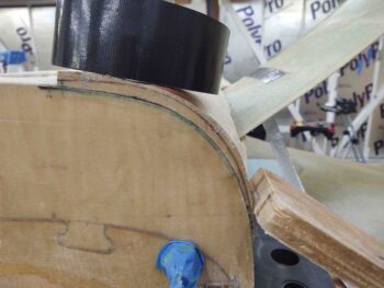
I figured out the lower left firewall “corner” section I needed to add back in order to align the bottom cowling front edge to the firewall/aft bottom fuselage. Again, part of the iterative process…. at least my iterative process.
After double-checking and verifying the section of firewall that needed to be added back to the firewall, I cut it off the original trimmed piece and floxed back onto the firewall. I then left it to cure overnight.
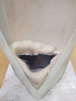
I then got to work on the final task to prep the armpit air intake scoops for mounting to the bottom cowling: filling in the hollow entrance lips with pour foam and creating a ramp to mitigate any turbulence of the incoming air.
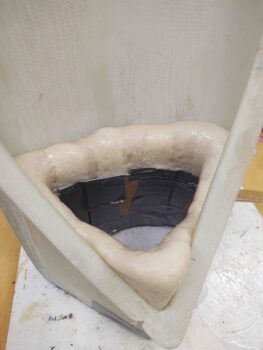
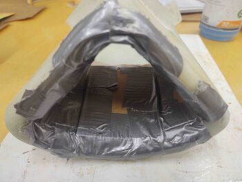
I started by creating a form out of thin cardboard covered in duct tape. I then secured that in place.
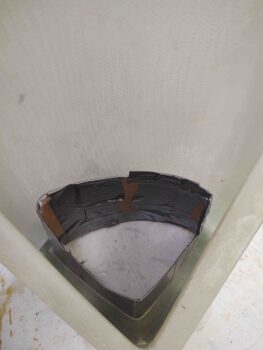
And whipped up some pour foam and poured it inside the form, which was subsequently inside the entrance lips.
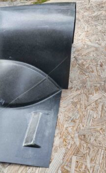
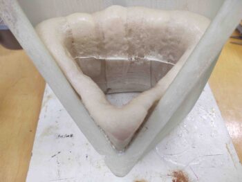
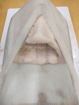
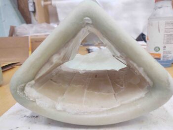
A bit later I removed the form, which gave me this to work with.
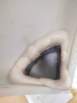
I then did the same thing on the other armpit air scoop, reusing the form from the first scoop.
Here’s a shot from the front side of the pour foam form, as well as a pic after I removed it.
As I go about the business of dialing in the intersection between bottom cowling and aft bottom fuselage/firewall/hell hole, I’ll also shape the pour foam to create ramps that converge with the inner walls of the respective air scoops. After which I’ll glass the bare foam to finish off the initial prep of these armpit air intake scoops.
THanks, pls disregard prior – you’d got good detail in the build log. Thanks, PK