
After getting back from Nick’s I was a bit tired from an active weekend and a good bit of traveling. Sadly I have to report that Nick’s plane was being a bit finicky engine-wise and he was having it checked over to make sure all was ship-shape before he sells it. Thus, no flying.
I of course still got my back-up Silver Bullet prop, in the original crate which is exactly what I want in case I ever need it shipped out to me post haste somewhere. I also bought the 1/2″ prop bolts from Nick at RR for less than half the price of new ones. Yes, the one downside since my primary prop has 3/8″ bolts… but remember, my prop extension has two sets of holes on the prop-mounting end: 1/2″ & 3/8″. Still, for a backup prop that’s in excellent shape (freshly painted and balanced), the same size and pitch as mine (66×75), for less than half the price new, I’m still calling it a good deal.
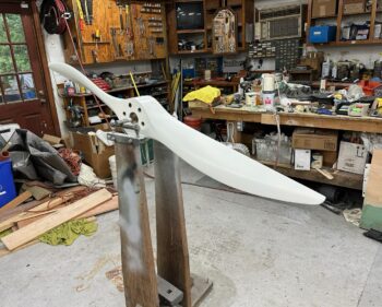
Nick also gave me his prop balancer shown in the pic above, as well as he’s sending me his wing leading edge light jigs and forms which I will use to create my wing leading edge landing/WigWag lights just prior to final painting of the wings.
Moreover, Jess and I had a great time visiting Nick and enjoying Charleston, so clearly the trip wasn’t a total bust.
Back in the shop I wanted to get some glass/CF curing, but didn’t want to take on any major layups.
At RR I talked with James Redmon and a Defiant guy who both used glass/CF for the base (bottom) of the armpit scoop baffles, or what I call “ramps,” and then both attached aluminum to the tops of these bases to allow for bending the top angled part of the ramp to modify the airflow. This will allow me to dial in the airflow to the cylinders without having to cut out the glass/CF only ramp, remake the ramp, and then install it again. The only different approach between these guys was James said use thicker aluminum, the Defiant guy used thinner.
On my spare set of paper armpit inlet ramp templates in the shop, I cut out bottom portion of each of the 4 respective airflow ramps (2 per side) and then set them on top of a 8.5 x 11″ piece of printer paper. I then spaced them as tightly as possible to get the required dimension down to 8.5 x 9.75″ for all of them to fit.

I then used my trimmed printer paper as a template to cut out 3 plies of CF and 2 pieces of peel ply, one for each side.
I wet out the first ply of peel ply and then wet out/laid up the 3 plies of CF on top of the peel ply (all on top of a piece of plastic to keep the layup surface clean).

I then finished the layup with the top/second piece of peel ply.

I covered the peel plied layup with a piece of plastic Saran wrap and squeegeed out all the bubbles and wrinkles.
I then placed a piece of flat aluminum sheet, and then two heavier steel sheets over top of the 3-ply CF layup to ensure it cured very flat. I then left it to cure overnight as I used Pro-Set epoxy.

I then blatantly copied my buddy Dave Berenholtz in how he created a template for cutting the propeller notches into the prop spinner. Except while he used mold release and laid up the template in one shot around his prop spinner, I didn’t want to deal with the hassle of prying off a singular fiberglass template, so I’m doing mine in 2 halves and then securing them together.
I started by taping up just over half of my spinner with gray duct tape.

I then gathered up all my smaller scraps of UNI and laid up 2-3 plies over the gray duct tape.

I then left it to cure overnight.

And with those bit of layups “in the oven” I called it a night. Tomorrow I plan to glass the other side and get busy on the aft intersecting edges of the top & bottom cowlings.