
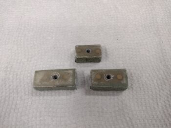
I started out today spending well over an hour making up the next round of 3 foam tabs for the GIB headrest surround cover. I ensured the lengths were correct, sanded the paint/glass in the correlating mounting spots on the headrest structure and inside the turtledeck. I made cutouts in the foam tabs to allow a flush fit of the #6 platenuts, cut the 1 ply of BID and peel ply for each and then micro’d the platenuts into the foam. I then laid up the BID, peel plied the layups, and weighed down the glassed foam tabs.
I’m fast-forwarding here about 5 hours to show you the foam tabs after cure & cleanup. I had sandwiched them between 2 yellow micro spreaders and under a heat lamp to ensure they stayed nice and toasty to cure in a warmer environment. Well, I must have moved the base of my setup slightly and the heat lamp lip slipped off a wood block I had on one side. The issue the much closer heat lamp caused was to heat up and soften the top spreader to allow it to lose its downward pressure. This allowed a bit of wonkiness with my nice tight layups… anyway, they are still light and strong as all get out: just ugly! haha
I wanted to get the armpit inlet front ramps’ aluminum vanes cut out and fitted before I glassed the final ramp in place on the aft right inlet. I had planned on using my band saw but the rubber surface on the bottom wheel broke and made my band saw currently inop. I resorted to using the Dremel with a cutoff wheel and cut the vanes out of 0.032″ 2024 scrap pieces from my VANs baffle kit.
As a reminder, when I was querying a Defiant builder at RR he said that he used very thin aluminum flashing from Home Depot and that it worked great… whereas James Redmon said to use 0.063″ thick aluminum for the repositionable vanes (the whole reason for using separate aluminum vanes here). I split the middle on their opinions somewhat with the 0.032″ vanes since I believe it will be plenty strong to withstand the force of the airflow. If not, I can always increase the thickness (but don’t see having to do that).
I then made the bends in the vanes on the metal brake, simply starting out with the degree of bend that Mike Melvill had labeled on each template: 20° bend on the right side and 15° bend on the left side.
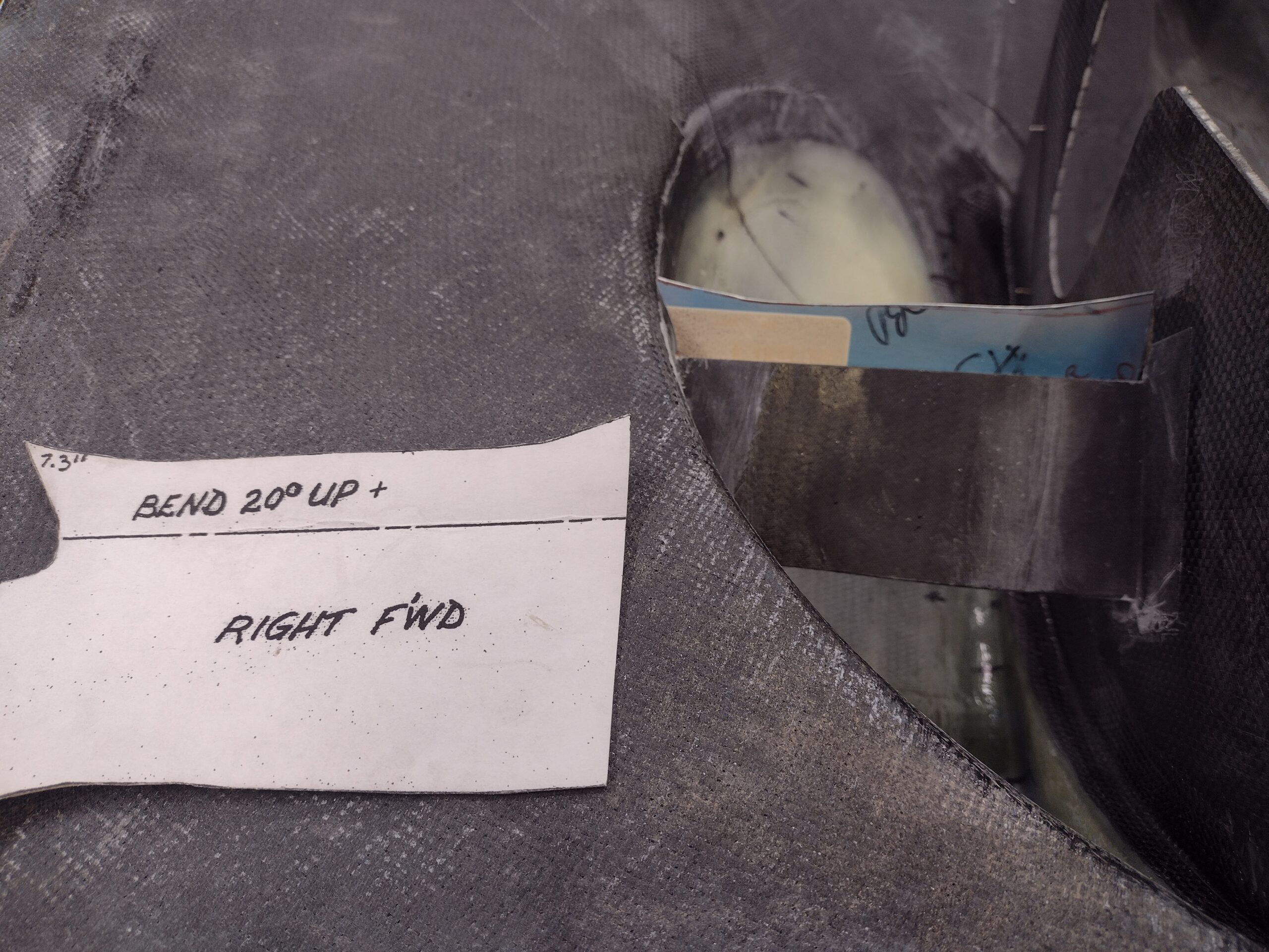
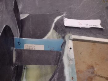
I had already spent well over 30 minutes trimming the aft right ramp to shape to fit in its new position about 3/4″ aft of where Mike Melvill had his aft right ramp. I had to move this ramp aft a bit to avoid the front cold air induction pipe. To compensate for the movement aft I will most likely angle the aluminum vane upward more than Melvill had his.
I also took a few minutes to trim about 1/4″ off the bottom of the “U” shaped notch in the right inlet inboard wall to provide clearance with the right front cold air induction pipe.
After cutting the glass and peel ply, and drilling 2 small holes in the inboard wall to support the inside edge of the ramp with thru-rivets, I laid up the glass and then peel plied it. As I did on the left side I first laid down a bead of micro to provide a smooth transition on the front edge and a significant fillet on the aft side. I’m using micro vs flox for both weight and also in case I need to reposition this ramp… I wouldn’t want to have to fight removing flox.
With the aft right ramp glassed in place, I then got back to work on the front ramp vanes. I measured and marked the rivet positions, then drilled those out. I had to do some fine trimming on the side edges of the vanes to get them to fit, and then I clecoed them into place.
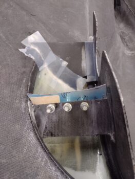
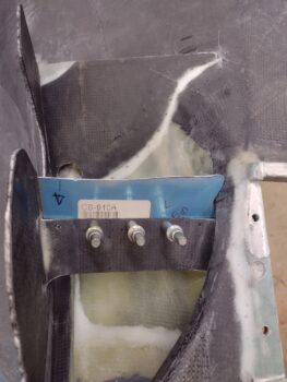
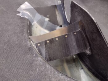
I then countersunk the rivet holes and riveted the vanes in place. Here we have the right inlet front ramp/vane combo.
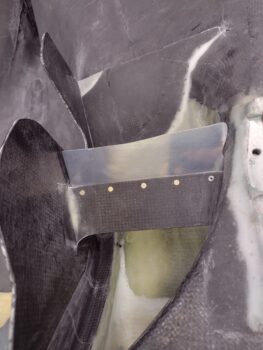
And the left inlet riveted front ramp/vane combo as well. You may note that the outboard side of the left vane was just a hair too wide for my rivet squeezer so I had to resort to a pop rivet.
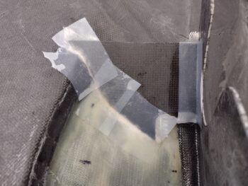
I spent the last hour in the shop ensuring my final positioning of the cured 3 foam platenut tabs were good before micro’ing them into place. As you can see I applied protective tape onto the GIB headrest gap cover at the screw positions and ensured that the foam platenut tabs were aligned with the holes in the cover. I then left the micro’d-in-place foam platenut tabs to cure overnight.
Tomorrow I’ll get the final BID tape laid up on the aft right ramp to officially have those installed, and then finalize the shape, position and install of the aft ramp aluminum vanes. I’ll also try to get the carbon fiber laid up on the GIB headrest gap cover since for now I’m not spending any more time on the GIB headrest cover in adding more screw positions… sticking with 6 screws total. After these tasks are done I’ll be positioned to start on the exhaust pipes.