
I started off today by pulling the peel ply, razor trimming the glass and cleaning up the layups that attached the right inlet’s aft ramp into place. Everything looked good thus far.
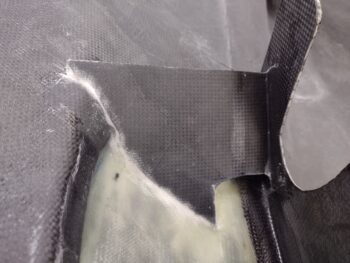
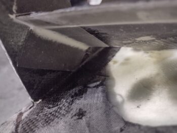
I then cut a small strip of BID and laid it up on the inboard underside of the right side inlet aft ramp. I employed a thin micro fillet on this bottom side corner just for a little added strength. To be able install the aluminum vane on this ramp in the ensuing hours, I used MGS with fast hardener. With this layup the ramp installs are “officially” complete!
I then got to work figuring out the shapes and configurations of the aluminum vanes on the aft inlet ramps, both left and right. I of course have the Mike Melvill templates for these, but as I’ve stated a number of times: with a different size engine and especially with cold air induction that drove minor moves in placement on nearly all these ramps, I certainly needed to tweak his templates for these aluminum top vanes to play nice with my engine.
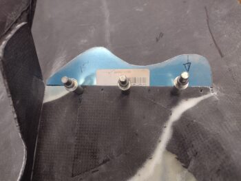
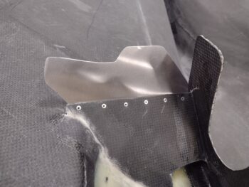
I started with the stock template (pic 1) and then over a few iterations dialed it into the final vane configuration (pic 2).
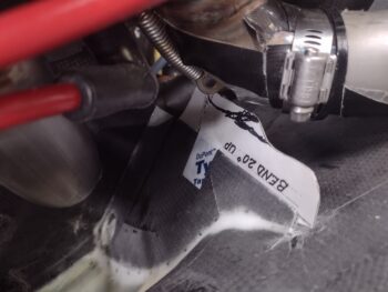
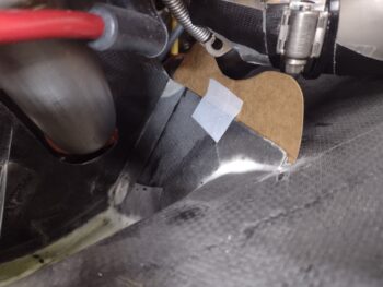
I then did the same thing on the right side: stock aluminum vane shape (pic 1) and after modifications to allow for clearance with the aft cold air induction tube and exhaust pipe (which I realized after the bottom cowl was on that the aft exhaust was a major cast member in this critically acclaimed drama!… pic 2).
I spent a good little bit cutting out the aft ramps’ aluminum vanes from scrap baffle 0.032″ 2024 and then bending them on the metal brake. I then removed the bottom cowl and hadn’t started on installing the vanes yet when I pulled the peel ply, razor trimmed and cleaned up the last layup on the inboard underside of the right aft ramp [pic looks the same as the layup pic did…].
I then trimmed, filed, drilled and clecoed the significantly modified (vs Melvill’s templates) aluminum vanes. Sorry, I couldn’t resist filling in the dog profile on the right vane… after I loaded the pics I realized the left vane looked like a hippo! haha (… going shop crazy!).
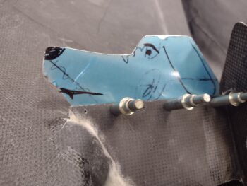
I then pulled the plastic and did a final cleanup on the vanes before riveting them into place. I guess I didn’t grab a shot of the left vane installed, but….
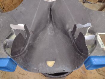
Here’s a shot of all the ramps and all the aluminum vanes installed on the lower cowling. TASK COMPLETE!
I then installed the bottom cowling back onto the bird. Probably as you’d expect, it takes a bit of jucking and jiving to finagle the bottom cowling into place now… it doesn’t just line up the flanges and plop on as it did before.
Here we have the left side aft vane in position, shot from both the side (pic 1) and from aft (pic 2).
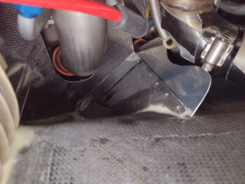
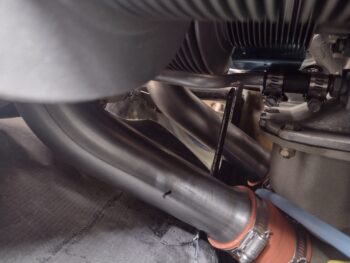
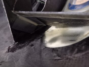
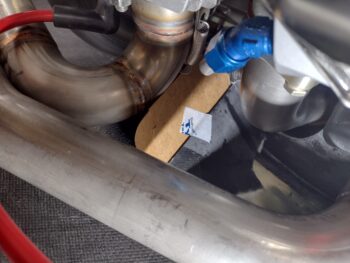
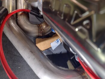
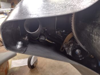
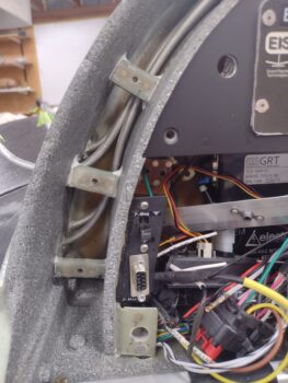
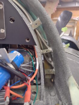
And the same for the right side, with a shot of the vane from the side showing clearances (pic 1) and from aft as well (pic 2). I will note that out of all these vanes, if any were prone to flex with my use of 0.032″ thick aluminum, it would be this one right here… since it’s quite a bit taller than the other vanes. I’m making a note of it so if I ever think flex may be an issue I’ll swap it out with 0.04-0.05″ thick material.
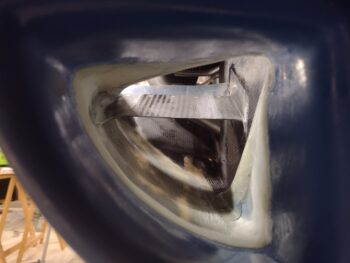
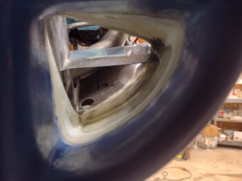
I then grabbed a shot through the front side of the armpit scoops to show what each side ramps and vanes look like from head on.
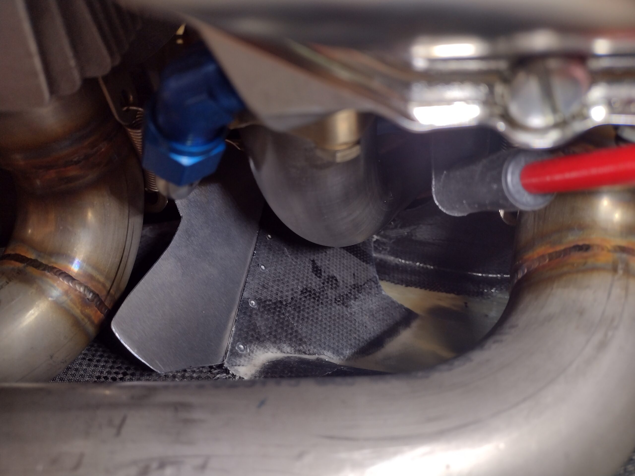
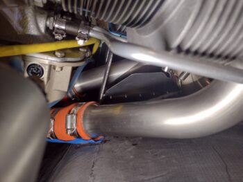
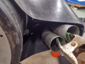
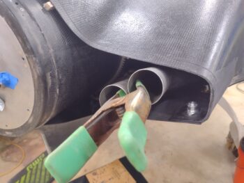
With the exhaust pipes mounted for the first time since (I believe) I finished the top and bottom cowlings interface, I spent a good half hour assessing the right exhaust pipes’ configuration. First, I determined that the gap between the spinner flow guide and inside edge of the first pipe (cylinder #2) needs to be 2.5″ (looking at 2.2″ on this dimension for the left side).
Next, even though the ends of the exhaust pipes appear too close to the cowling edges, if I trim them so the pipe openings are 2″ before the end of the cowling then elevation-wise they’re pretty much center of mass in the opening. That being said, I may need some welding done just at the tips to get the actual exhaust pointed in the correct direction (more towards the spinner/prop intersection)… but beyond that: NO welding or redoing the pipes required on the right side!
The left of course is a whole different story. I’ll need multiple iterations of cutting and welding these pipes to get them squared away in relation to the cowls… but with my exhaust welder James, I’m confident that over a week or two we can get this job done!
It was fairly late in the evening when I finally got around to pulling the GIB headrest gap cover (technically the “fuel tank vent lines cover”) off to check out the foam platenut tab installs. As I did on the first 3 tabs I worked the screws in and out of the platenuts a good couple times before removing the cover.
Here we have the 2 new top foam tabs on the right side (pic 1). And the added new top foam tab on the left side (pic 2).
Now, the final clamping —with the screws installed— of the thin cover added a little buckle to it towards the top, so I’ll need to trim out about a 1/4″ and re-glass it to remove that distortion. After I get it (re)dialed in I’ll lay up the top CF ply and call it good! BTW, there will be a strip of velcro on the very top dead center that will secure that portion and keep it from vibrating.
And after another long build day, I called it a night.