
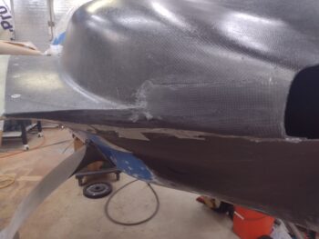
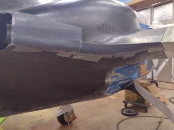
This morning I started off by pulling the peel ply from the top cowl left/bottom/aft side’s “final” CF layup. Of course with caveats that I may do a small filler layup in a spot or few. I then cleaned up the edges and small bits of overhanging CF. Again, I’ll need to lean on micro to completely clean up the surface, but it looks really good.
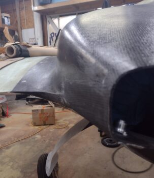
Since the pic above seems to make the side of the big aft cowl opening look like it slants outward —just perspective— I grabbed this shot below to show that isn’t the case.
I then pulled the peel ply of the right side’s 3-ply CF layup, and cleaned it up for another round of CF.
I then assessed the surface, measured, made templates and cut out CF plies for the final layup on this right side.
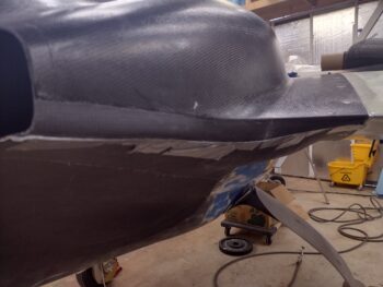
Then, again using MGS 285, I laid up the puzzle that is the final layup on this right side… with the same caveats as the left side of course!
I then peel plied the layup.
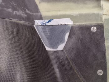
I found my next task laced with a bit of irony. My reasoning for installing a screw on each side of the leading edge of the top and bottom cowlings is based on a recommendation from Wayne Blackler, who himself had lost CAMLOCs due to the pressure from the oncoming air. Having armpit scoops on the bottom cowling especially, and know that the air flowing over the curved wing shape of top cowling wants to pull the cowlings out, I thought it a good idea to follow Wayne’s advice. That was Round 1 over 10 years ago.
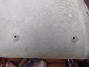
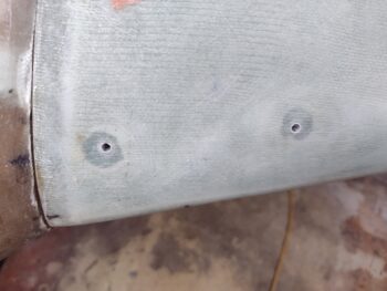
Circle back around to these screws, and Dave Berenholtz was having a recent conversation with Wayne about mounting depths for various screws. Wayne noted to Dave that going into composite material it’s 66.7%, so for CF it needs to be 3/2 X countersink depth. The example Dave gave is that a 3/16″ MS24693 screw has 0.080″ countersink depth, therefore you need 0.120″ thick CF. The main issue is that the hole grows into a big dish and alignment gets sacrificed.
The thickness of my cowling varies quite along the front edge. At the screw holes positions one side is right at about 0.070″ and the other is around 0.074″. I told Dave I’d probably just use button heads at these points to get this bird in the air. That’s when Dave got ruthless, using intense peer pressure tactics to let me know if I did that, all the other Long-EZ owners would point, sneer and laugh at my bird for looking so dumb… (hahaha! Just kidding!) He did note that it’s better to do a little work now and use countersunk screws for it to look classy vs screws that look like an afterthought.
Big sigh…. Yep, he’s right.
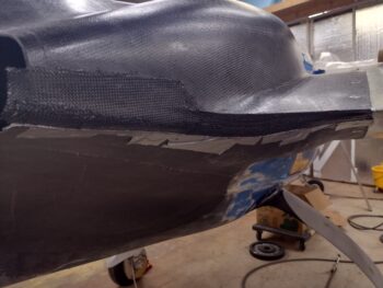
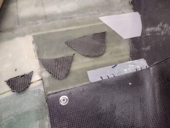
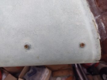
But I did compromise in only adding 3 more plies. At 0.011″ thick per ply I’m well over 0.1″ on each side now, and to minimize a thicker bump requiring even more micro fill than I’ll require on this bird, I stuck with that configuration: as you see below. If I find the amount of meat is lacking, then I’ll throw another ply over all of these overlapping further onto the cowling.
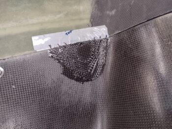
Here we have the 3 plies CF for the left side screw hole, which I then wetted out. Yes, I know the layup is a bit wet, as I used the peel ply to soak up the excess epoxy.
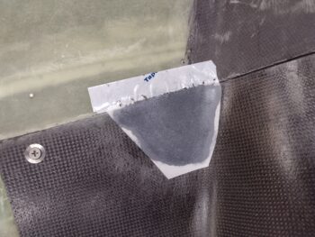
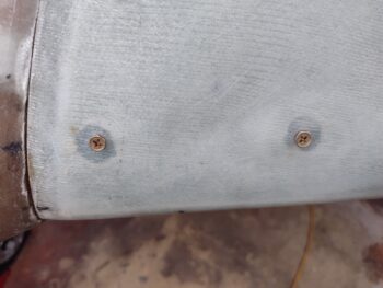
I then did the same thing on the left side. Here are both sides with the 3 plies CF laid up and peel plied.
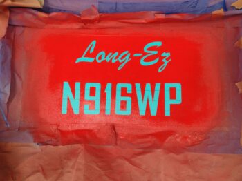
I then spent the next hour for arts n crafts… gotta have some creativity on these birds! I used Jess’s Cricut that she has at my house to make up another set of vinyl letters (just like the landing brake) and then spent a good little bit centering them and getting them onto the curved inside surface of the aft nose/avionics cover. I was going to do a round of painting, but it was getting later in the evening and I need to do a decent bit of sanding and prep before the next round of paint goes on… so I figured starting tomorrow that I would do a bit on this each day until this sideline project is finished.
Instead of doing the next round of painting on the aft nose/avionics cover, I decided to knock out another small task on my list: opening up the buried threaded inserts on the leading edge of each wing for the baggage pods. I’ll note that all the other threaded screw inserts on the bottom of the wings are open and ready for the baggage pods (I know, a bit out of order but I wanted to install those while the wings were inverted).
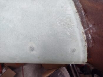
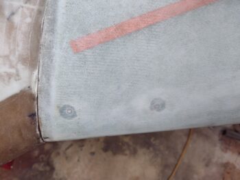
Opening up access to the threaded inserts here was really like opening up a time capsule. You see, early on in my build I learned a great hack from Marco on filling threaded inserts, platenuts, rivnuts, etc. with plastic Saran wrap to keep the epoxy, micro or flox out of the threads. And since that little hack worked such a treat, I’ve been doing it ever since. So whenever I drill into a threaded insert, I expect the drill bit to grab a bunch of plastic wrap and to pull a big plug of it out. It’s satisfying in the same way pulling peel ply is!
But these were finished before I learned that hack. When I drilled the holes out of the overlying glass, I saw nothing but threads… what the? Then I remembered I just used a small roundel of duct tape over the hole to protect the threads. Apparently that worked a treat as well… the crazy little things in these builds.
I then rounded up some test bolt/screws to thread into the inserts to ensure all was good… perfect. No issues whatsoever. Task complete!
Tomorrow my goal is to start back on the exhaust pipe clearance assessment and working the bottom cowling baffles/ramps. In addition I’ll make another attempt to contact my MIA exhaust pipe welder, James. I’ll also note that I reviewed the install manual for the VAN’s O-320 engine baffle kit I have and will most likely start playing around with that a bit as well. Moving forward . . .