
Today I was able to knock out what I consider a significant milestone regarding the engine and this airplane build: I finally ground out a decent chunk of the lower right engine mount flange to provide access and clearance for the fuel feed hose from the engine driven mechanical fuel pump to the Fuel Injection Servo… more on that in a bit.
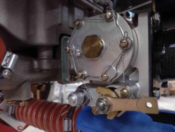
I think it was one of the quality experts of the 60’s or 70’s that said, “40% of work is rework.” Well, as a nod to them I reworked putting the fuel injection servo fuel inlet fitting BACK on the left side. I then safety wired the fuel inlet plug on the right side.
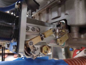
In addition, I mocked up the fuel line to get a good idea of where I can secure it with an Adel clamp and determined that when I create my mixture lever control cable bracket I will add a little tab that I’ll mount an Adel clamp on to secure the fuel feed hose.
I then spent a little bit of time doing more of a cleaning and aesthetics task on the motor. The hose clamps they used on securing the rubber-type junctions between the cold air plenum and the cold air manifold pipes are way too long and I can see them vibrating around plus just looking ugly… to me anyway.
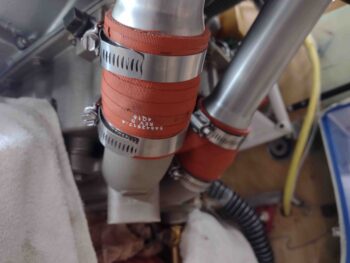
So I took an aluminum can and cut the middle area out, folded it over and used it as a protective backstop to lop of these excess, unsightly segments of hose clamps.
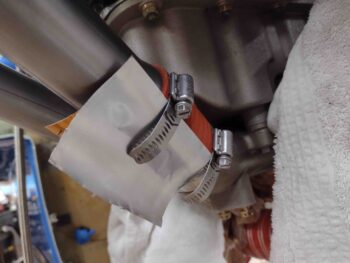
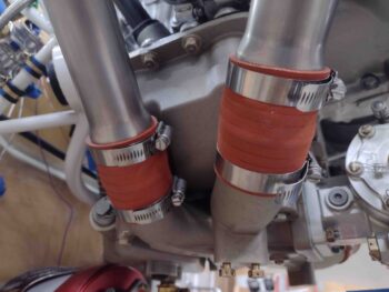
Here we have the left side of the engine with the hose clamps trimmed down.
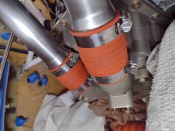
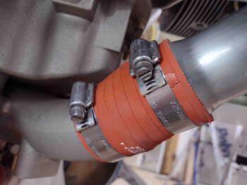
And the hose clamps trimmed on the right side as well. Much better IMO!
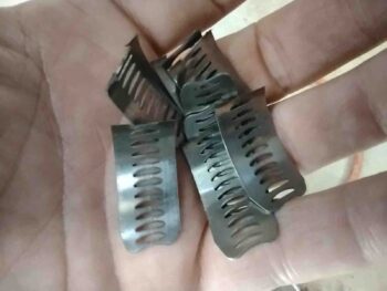
And here are the offending excess hose clamp pieces. I weighed them out of curiosity and am getting a whopping 1/2 ounce of weight savings.
With my trusty Dremel Tool still plugged in with cutoff wheel installed, I tackled the big issue that has been nagging me since I mounted the engine to the engine mount… trimming away a good part of this flange at the lower right corner of the engine mount. I’m not sure why the flange is there or what purpose it truly serves, clearly reinforcement of some type. I’ll have to ask Randi & Chrissi someday why they added it… maybe it’s a Cozy thing.
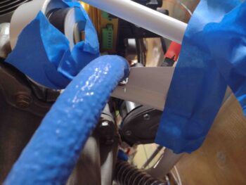
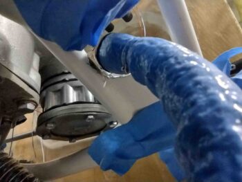
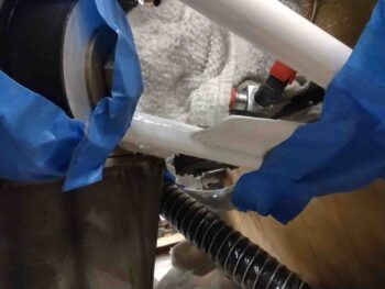
Regardless, the aft inch of this flange was in the way and had to get removed in order to allow me to run the fuel feed hose OVER the top of this engine mount tube (the lowest horizontal tube in the pic below)… because there was about zero clearance when I ran the hose on the inside of the tube. I’ll note that I also experimented with turning the fuel pump fitting upwards and running a 120º fitting, but the angle would have the hose really jammed up against this tube. Also with the fuel pump fitting more vertical a 90º hose fitting would push the hose forward and I would either need to remove a much bigger chunk of this flange, or notch it in the center to allow the hose to traverse between these angled motor mount tubes.

Thus with the fuel pump fitting facing aft and a bit more horizontal, I can use my 90º fitting and come off it “sideways” to then drop over that last inch of tubing which again requires as minimal of flange removal as possible…. less work while maintaining the strength that that flange provides.
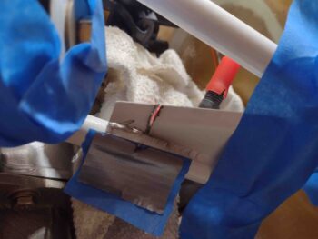
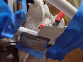
As you can see, I taped up a bunch of items in the surrounding area and covered others with shop rags. I then cut into the flange and along the weld at the mount cross tube.
A couple of wiggles and the flange piece came out. Now for some cleanup.
I used the Dremel tool some more to judiciously remove more of the remaining flange and weld steel in successive steps.
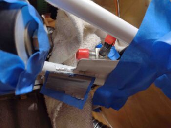
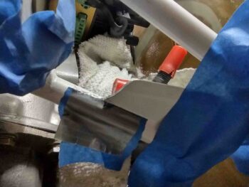
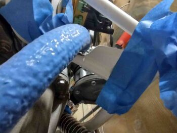
I then mounted the old hose —which I can’t use with the fuel injection servo facing aft— and checked the clearance… which there is some underneath the hose, but clearly the hose is touching on the front side (right) of it against the flange.
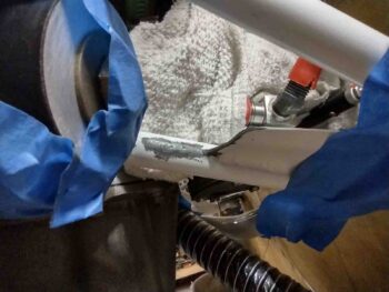
I then remarked the flange for a bit more trimming . . .

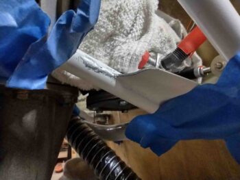
And again used the cutoff wheel on the Dremel to trim down the flange a bit more.
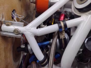
Ahh, much, much better… finally! 5 years later and I’m getting there… ha!
I then used some hand files to clean off the remaining raised steel.
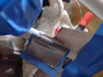
And then applied a couple coats of primer.
Since the primer is dark gray, it took 4 coats of white paint to get the trimmed steel back to white. I’m applying spray paint with a brush here so it doesn’t apply as well as if I sprayed it of course. But it definitely is a good enough primer & paint job to keep corrosion at bay and make the mount look “normal” in a very inconspicuous area of the engine.
This was a huge task that really needed to be completed for a worry-free run of that fuel line.
With the white paint drying on the engine mount, I set my sights on another somewhat esoteric task that needed to be completed: the adding of a ground wire to the GRT oil pressure sensor (the bigger one on the left). I know a number of people braze a tab onto the oil pressure sensor, but since I don’t have any I thought I would try my luck at soldering the tab on… which I have read reports of folks doing as well.
However, the oil pressure housing proved to be nothing more than a big aluminum heat sink and the solder wouldn’t flow out nearly enough to secure the tab. After just a few minutes I punted on this idea.
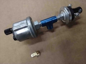
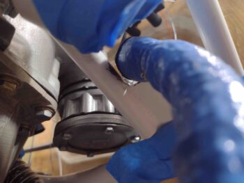
I knew I needed to run a ground wire to the Common terminal on my other (B&C) oil pressure sensor (for a backup oil pressure warning light and Hobbs Meter), which is isolated electrically from the rest of all the metal parts of this assembly —which a continuity check showed are all electrically connected.
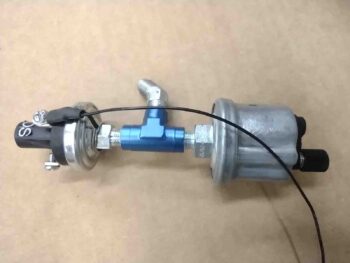
Since I had my safety wire kit out for the fuel injection servo inlet fitting re-swap, I simply wound a length of wire around a small groove at the base of the B&C OP sensor and used my safety wire tool to twist the wire tight, around and into the groove at the base. I used 3 loops. After adding some spiffy heat shrink, I then terminated the safety wire along with a 22 AWG black ground wire into a screw post fitting that I then secured via a screw to the Common terminal.
Voila! I piggy backed off the B&C oil pressure sensor ground circuit to provide the ground for the GRT oil pressure sensor on the opposite end. As per one of our mantras in Bomb Squad: “if you ain’t cheatin’ you ain’t trying!” <wink>
I then mounted the oil pressure sensor assembly onto the engine mount frame just above the vernatherm on the left side. The spacing was too tight for me to actually connect the front Adel clamp, but the configuration provided me with enough data to now know my next steps for creating the cross connect hose from this sensor block to the oil pressure out fitting on the engine accessory case. Very good actionable intel here!
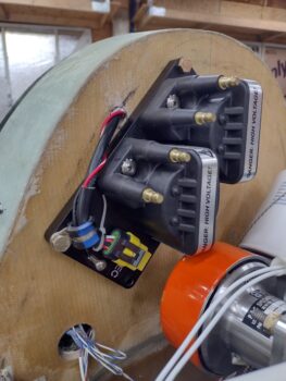
My last task of the evening was to crack open the GIB headrest to assess whether to run the Electroair coil pack wires through the firewall at either point A or point B. Although point A was tight since it was right at the inside wall of the GIB headrest, I was able to knock down my drill bit diameter to a bare minimum required 3/8″ and drill at an angle.
I had removed the coil pack and before remounting it on the firewall I drilled out the corner Adel clamp holes to 1/4″ diameter. I then remounted the coil pack with the Adel clamp mounted in place as well. I then ran the wiring bundle through the firewall into the GIB headrest where the majority of my engine electronics reside.
Another task off the list as I inch closer to finalizing this engine install!
And yep, it was late, so I called it a night and headed into the house for yet another late dinner.