
I started off today by finalizing yet another ACS order, trying not to miss anything since they seem to have the highest shipping costs on the planet. I then pulled the trigger.
I also tried to get the exhaust pipe bubbas on the horn, but no joy there.
I did do a bit of research before heading out to the shop to start working on the fuel injection servo fuel lines, both the feed from servo to the spider, and the main hose coming from the mechanical fuel pump to the servo.
My intention was to make up (or modify) both fuel hoses and be done with all this by the end of the day. However, real world configurations and angles have a way of messing up the initial plans we have about certain tasks once we dig in and unearth some facts.
That being said, within just a minute or two I realized that for the -4 hose between fuel servo and spider flow divider I would need a 45º hose end fitting to connect it to the servo outlet fitting. I don’t have a 45º -4 hose end fitting, so on the to-buy list it went.
Pressing forward, I then SUMMARILY (Definition “suddenly, without discussion, without delay”) decided that as a prerequisite to working the fuel feed from the mechanical fuel pump to the fuel injection servo, I would swap the fuel input fitting on the servo from the left side to the right side.
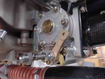
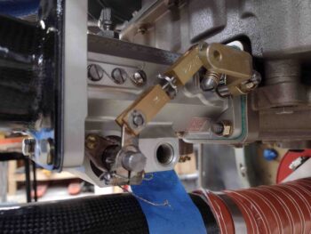
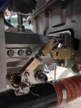
Here we have the fuel inlet fitting on the left side of the fuel injection servo.
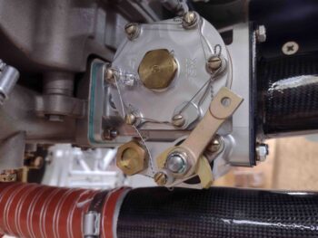
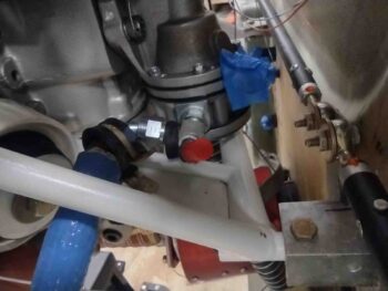
And the fuel inlet plug on the opposite side of the servo, over on the right.
The SilverHawk manual says to remove the inlet fitting first, along with the filter screen and spring behind it before removing the plug on the opposite side. I did that here:
. . . and then removed the plug on the right side.
Note how you can see all the way through the servo body when all the fuel inlet fitting components are removed.
I then installed the plug on the left side, torqued it to specs and safety wired it in place.
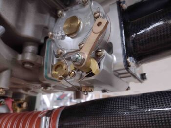
I then installed the spring/screen and inlet fitting on the right side, and also torqued it to specs.
Whew… good job Wade! Task complete . . .
or so I thought.
As the title of this blog states: “Bad assumption” . . .
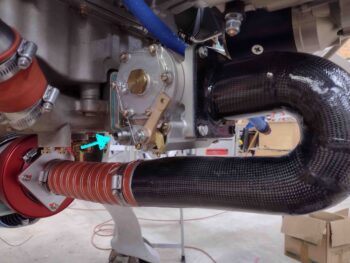
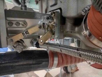
I then started working on the fuel line that will feed the servo from the mechanical fuel pump. After installing the old hose —which is too short for the now aft-facing servo— and making my initial observations and notes, I then turned to the other end of the hose.
But first, I’ll remind you all that the mechanical fuel pump is on the right forward side of the engine, so it makes total sense to have the fuel inlet of the servo on the same side. . . .
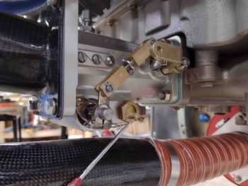
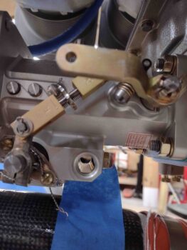
However, when I simply went to mock up how the fuel feed hose would attach to the servo’s fuel inlet fitting, I realized that no matter how I planned to route it, without getting ridiculous, I had a clearance issue with the servo throttle lever.
After a good bit of time pondering it, I then went inside and updated my Fuel Injection Servo mounting PowerPoint and printed it out since it has all my notes on installing the servo for each Course Of Action (this configuration is COA 2). Back out under the engine, looking at and assessing different possible angles of how the throttle cable actuator arm would connect to the servo throttle lever, trying every possible machination, I finally came to the conclusion that I just needed to think outside the box.
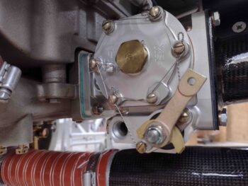
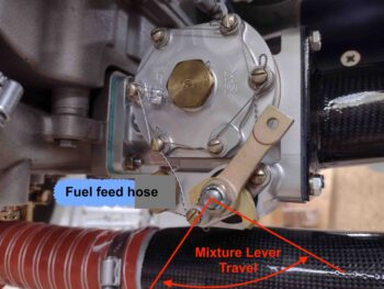
What does “thinking outside the box” in this situation entail? Well, the answer is a simple and interesting one: MOUNT THE FUEL FEED HOSE TO THE SERVO FUEL INLET ON THE LEFT SIDE OF THE SERVO! (Where, I’ll note, there is NO clearance issue with the servo fuel mixture lever).
Doh!
Ok… so to get my hose end fittings & components in hand as quickly as possible I then went back into the house to spend a good hour researching and finding the best components for my requirements before pulling the trigger on a Summit Racing order.
Back out in the shop I dumped the fuel servo hose project completely for now and focused on another task: the routing for the wire cable coming out of the Electroair electronic ignition coil pack going through the firewall.
Now, I will have 2 separate CPC connectors —one on each side of the firewall near the upper mounts— through which nearly all the engine-related wiring will traverse the firewall. Again, the pair of connectors is to help in maximizing my personal requirement of making engine removal and mounting as pain & trouble free as possible.
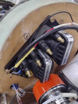
But then why are these wires going straight through the firewall? That’s due to the Coil Pack being mounted directly to the firewall. When you think about it, clearly the coil pack stays in place when the engine is removed, so the wires won’t/can’t go through either connector if this is the case… the wiring has to be separate from the other connector wires and thus hardwired through the firewall.
Now back to the story at hand. On my firewall passthrough diagram I have the wire pass-thru hole shown on the bottom edge of the coil pack. However, with real word physical constraints rearing their ugly head once again, the wire bundle is simply too thick and rigid for me to be able to radius it to go into a hole at the bottom. It has to go either along the top long edge at point “A” or at the top short edge at point “B”. I’ll figure out which wire pass-thru point is best over the next day or two (as well as swap the servo inlet fitting back to the left side!).
So with a lot of background research, etc. compared to actual little in-shop work done today, I called it a night and headed out for a late dinner.