
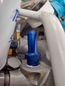
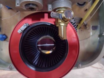
I started out today by working on the installation and configuration of the external vernatherm. The install seemed cut and dry at first, but when I mocked up the oil cooler position I realized that I needed to twist the vernatherm with the aft/upper side moved inboard and the other side vice versa…. not much mind you, but enough to be noticeable.
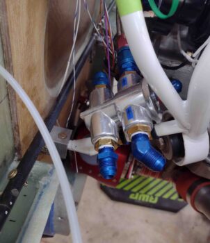
To twist the external vernatherm into place, I simply remounted the bolt on the aft Adel clamp so that the tab of the vernatherm sat inboard of the aft Adel clamp, while it remained outboard of the forward Adel clamp. This was just enough of a twist I need to better align the hoses going to/from the oil cooler.
I’ll note that I also spent a good bit of time back in the house diagramming out 2 different install configurations for the external vernatherm, with the second install option possibly needing to be implemented to get the oil lines optimized going in & out of the engine accessory case. The primary difference between the two options is the first one —what I have now— has the end cap of the vernatherm facing upwards, while the second option would be to flip it over. This flips the hot (out) and cold (in) sides and would be implemented mainly to keep the hose run configurations optimized and out of each other’s way.
I’ll be able to determine which install configuration will be best when I remove the engine from the firewall to finalize the front of engine hoses, wiring, cooling tubes/brackets, sensor, fittings and components install… including hose and wire cable routing and securement.
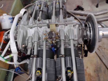
I then focused on removing the current brass 3/4″ OD crankcase vent fitting to replace it with a 5/8″ OD aluminum crankcase vent fitting.
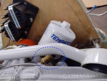
However, I ran into a slight issue with this task. Interestingly the 3/4″ OD hose fitting uses a 3/4″ socket/wrench, while the new 5/8″ OD hose fitting requires a 15/16″ socket/wrench. Clearly to torque the new fitting to specs I needed a 15/16″ deep socket… so out I went again for a multi-hour tool and hardware run.
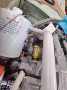
Upon returning back to the shop, I promptly removed the brass 3/4″ OD fitting and installed the new aluminum 5/8″ OD fitting after gooping up the first few rows of threads (from the second thread in of course).
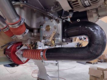
If you’re wondering why the swap, I’m going old skool and using a 5/8″ tube ran along the right exhaust pipes to carry out any engine crankcase vapor. Previously I was going to use a Slime-Fighter but decided against it… and, you guessed it! The Slime-Fighter uses a 3/4″ OD connection.
I then took a little bit of time to knock out what I should have done weeks ago: install the cylinder desiccant plugs. Nuff said.
My next task was to trim a bit of an angled edge on the oil quick drain fitting. I marked this up while the SCEET tubing was in place. This specific trim will do 2 things. First, it will provide clearance between the oil quick drain fitting and the SCEET tube. Second, it will allow me to slide a tube onto the oil quick drain fitting to drain the oil during oil changes.
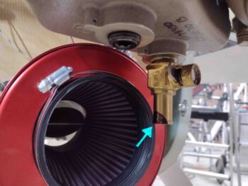
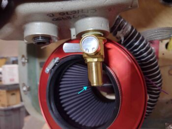
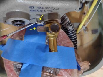
Before I got started trimming the inboard edge of the oil quick drain fitting, I figured it would be a great time to drill a 1/16″ hole in the handle of the oil quick drain to allow me to safety wire this sucker closed to ensure all is good during flight. As you can see by the arrows, the safety wire will spiral up for one loop around itself and then be secured to the bottom of the engine oil pan.
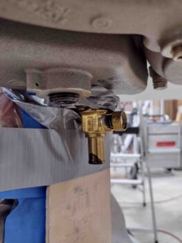
 After my drill job, I then prepped the area for trimming the oil quick drain fitting by duct taping a piece of wood behind (“forward”) of the oil quick drain fitting.
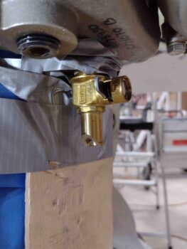
I then spent about 10 minutes with the Dremel Tool trimming the inboard lower edge of the oil quick drain fitting at approximately a 45º angle.
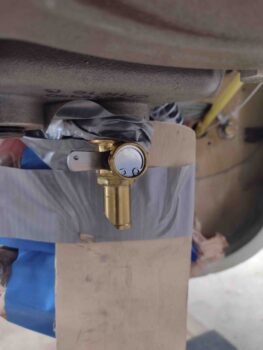
Here’s another shot of the oil quick drain trimmed at an angle.
I then took a bit of time (and heat) to back out the lower left stud that I had previously installed into the Superior cold air plenum. I had drove this stud in just a bit too far, and needed to back it out about 0.2″… with a good application of heat and tripling up the nuts on the stud I was able to get it backed out.
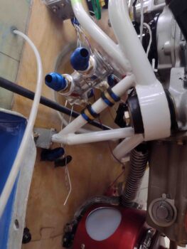
I then cleaned up the plenum-to-FI servo interface and placed a gasket in position.
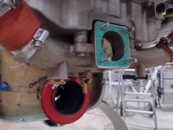
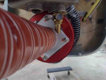
I then remounted the air induction system for another test fit. As you can see, it’s all fitting pretty darn well [Note the orange torque seal on the SCEET tube adapter hardware].
And here’s a shot of that trimmed oil quick drain… nice and clear of the SCEET tubing!
And with that folks, I called it a night!