
Although I got no real traction, today was actually all about working my exhaust pipe issues with the clearance they have with the lower cowling. I attempted to contact Clinton at Custom Aircraft Parts a few different times today to discuss my exhaust pipes but never got in touch with him. So I sent an email.
I then focused on other areas of the engine. First, I finalized the install of the SCEET tubing adapter I machined that allows me to attach the SCEET tubing from the Fuel Injection Servo air induction tube to the RAM air can.
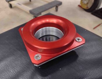
I first trimmed the corners of the SCEET tubing adapter to match the chamfered corners of the interfacing RAM can mounting plate. I then spent a little bit of time wet sanding the face of the adapter with 220 grit sandpaper to clean it up considerably so that it looks presentable… don’t want sloppy looking engine components!
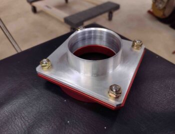
Using new stainless steel screws, I then mounted the SCEET tubing adapter to the RAM can mounting plate. I first installed a gasket, and with Loctite on the threads I torqued the nuts to spec.
Here we have the inside of the RAM can mounting plate. Note the machined bellmouth inlet where the air enters the SCEET tubing. And although not highly visible, there is knurling around the outer edge of the vertical raised portion to grip the inside rubber flange of the K&N filter. This rubber flange is what drives the requirement to use countersunk screws here since there’s no room nor clearance for standard nuts or bolts. Speaking of nuts, since these are course threads on the 82º countersunk screws, I’m using Grade 8 nuts here.
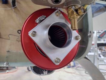
With the ever present tight clearances in the engine compartment, the same of course applies here. I mounted the SCEET adapter in a diamond configuration so what would be the top right screw/nut does not interfere with the oil quick drain. I’ll point out that this is the first time in recent pictures that the hose clamp securing the K&N filter rubber flange to the RAM air can mount is visible… since I just put it back on.
[Note that even the oil quick drain will get a bit of a trim on the bottom inboard edge where about 0.3″ will be removed at a ~45º angle to allow clearance with the SCEET tube PLUS allow sliding on tubing whenever oil drains are completed].
I then remounted the SCEET tubing and Fuel Injection Servo air induction tube to the RAM air can with a slight adjustment to the SCEET tubing placement (this is a recycled photo from yesterday… I didn’t take a new one).
I spent a good portion of the day building some of the final (hopefully!) buy lists for fittings, etc. and perusing a few local “Aviation Parts Depots” (aka Hardware Stores) looking for a couple of NPT fittings. I guess the supply chain issue is still in play with some stuff because I just refuse to pay $30 + way bloated shipping costs for an aluminum fitting on ACS (that cost less than $10 a couple years ago) when I can slip an extra 90º brass street elbow into the mix for less than $5 to get to the same end result.
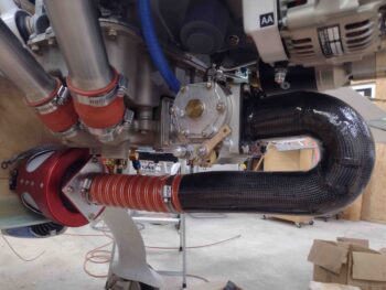
I then pulled out all my thread goop (Permatex #2, Permatex Thread Sealant with PTFE, Loctite 567, etc.) and torque sheets and got to work building, first, my external vernatherm (lower left in pic below) and then the oil pressure sensor block (upper right, same pic).
I used lower profile brass NPT reducer fittings on the vernatherm since these brass guys significantly minimize the width of this entire assembly (space is gold). Admittedly the torque listed on the vernatherm instruction sheet was 28 ft lbs, and I only got that on two before they bottomed out, while the other couple were within 2-3 ft lbs of that. I’ll keep my eye on these to ensure they don’t back out over time, but I’m confident that they are solidly installed. I then gooped up the threads and installed 3 straight nipples and one 45º to connect up the oil lines.
The 2 holed flanges on the opposite side of the vernatherm are drilled out for 1/4″ bolts. Thus, I took two -9 Adel Clamps and drilled out the holes to 1/4″ as well and further assessed that I need two AN4-6A bolts for installing the vernatherm via the Adel Clamps onto the lower left cross brace of the engine mount.
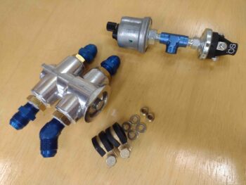
I then gooped the threads and installed both of my oil pressure sensors into a Tee fitting that will connect up to the engine oil pressure port (with a restricted fitting installed). I of course torqued these guys to spec. The final connecting fitting on the Tee will most likely be 90º (remember this is pressure, not liquid flow) and will be determined when I go final as I optimize the hose connection configuration.
Why 2 oil pressure sensors? Well, the big silver colored guy is for the GRT Engine Info System and will display oil pressure on my EFIS displays. The smaller black OP sensor on the right side is from B&C and has both NO/NC connections on it with either of those circuits closed depending on whether there is oil pressure or not. When there is oil pressure (clearly engine is running) then the closed circuit drives a Hobbs meter. When there is NO oil pressure then the other side circuit closes and lights up a separate <non-EFIS> “Oil Pressure” warning light on my AG6 warning annunciator.
Finally I’ll note that I’ll be mounting the oil pressure sensor block onto the frame of the engine mount, to facilitate much faster and easier removal of the engine whenever that might be required. Further still, I actually had the oil pressure sensors installed into a 3-port manifold block, but that proved much more cumbersome to mount onto the engine mount frame… so I punted and went with the Tee fitting.
Tomorrow I’ll continue to work sensor blocks, fuel and oil hoses, etc. as I work to get resolution on my exhaust pipes.