
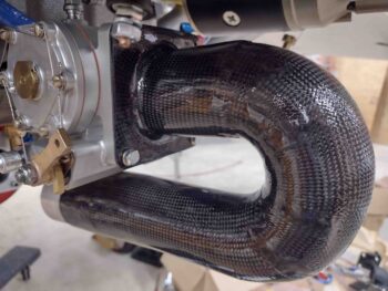
I actually started this clear-coating process yesterday: I hit the air induction tube with 2 coats of clear coat and let it cure overnight.
Today I wet sanded the clear coat with 320 grit sandpaper before then again shooting 2 thicker coats of 1K clear.
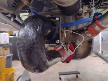
A few hours later, after a good initial cure, I mounted the freshly clear-coated Fuel Injection Servo air induction tube.
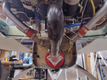
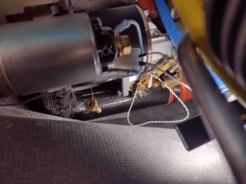
I then trimmed and mounted the 9.5″ long segment of SCEET tubing between the RAM air can and the air induction tube.
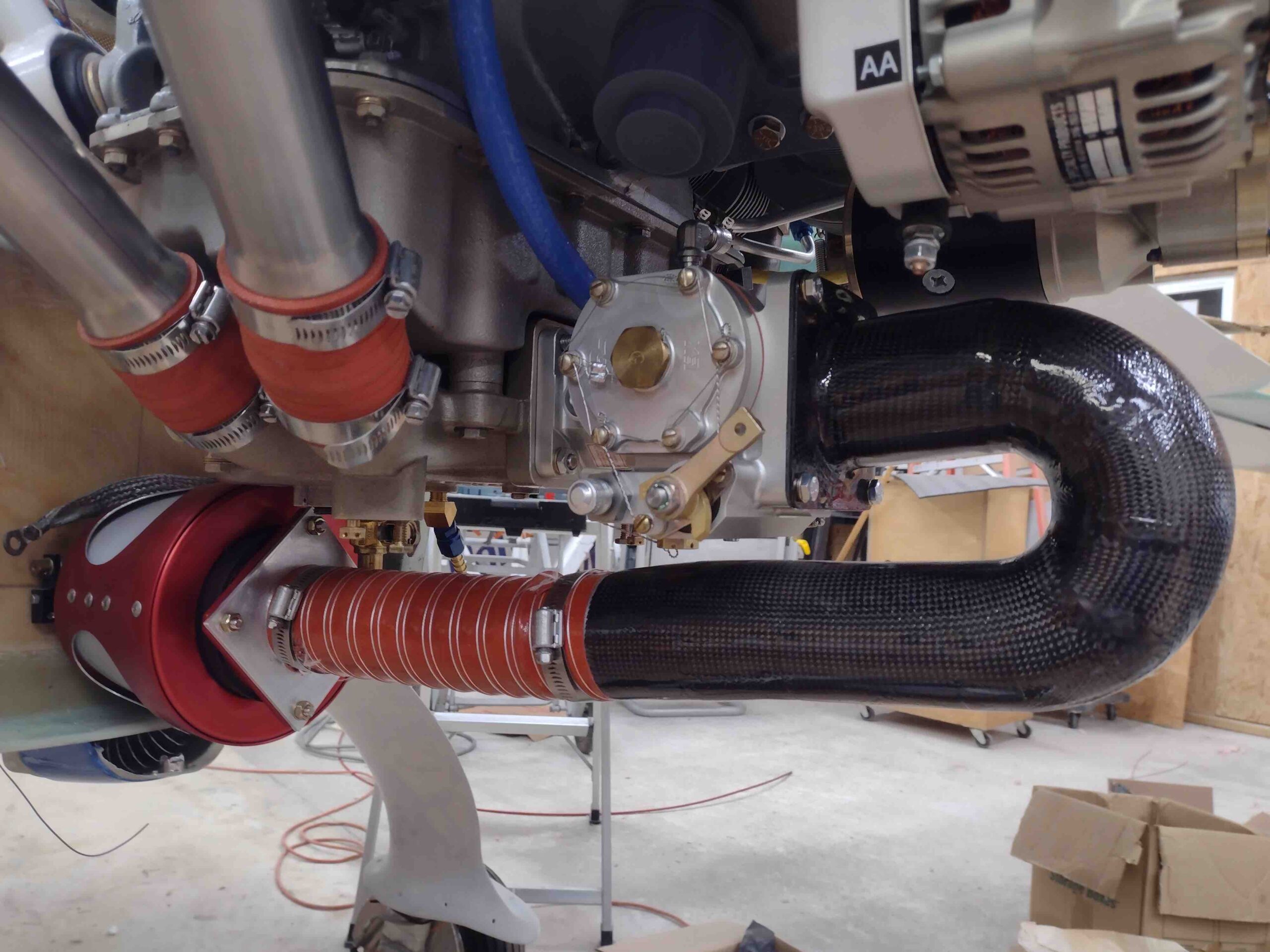
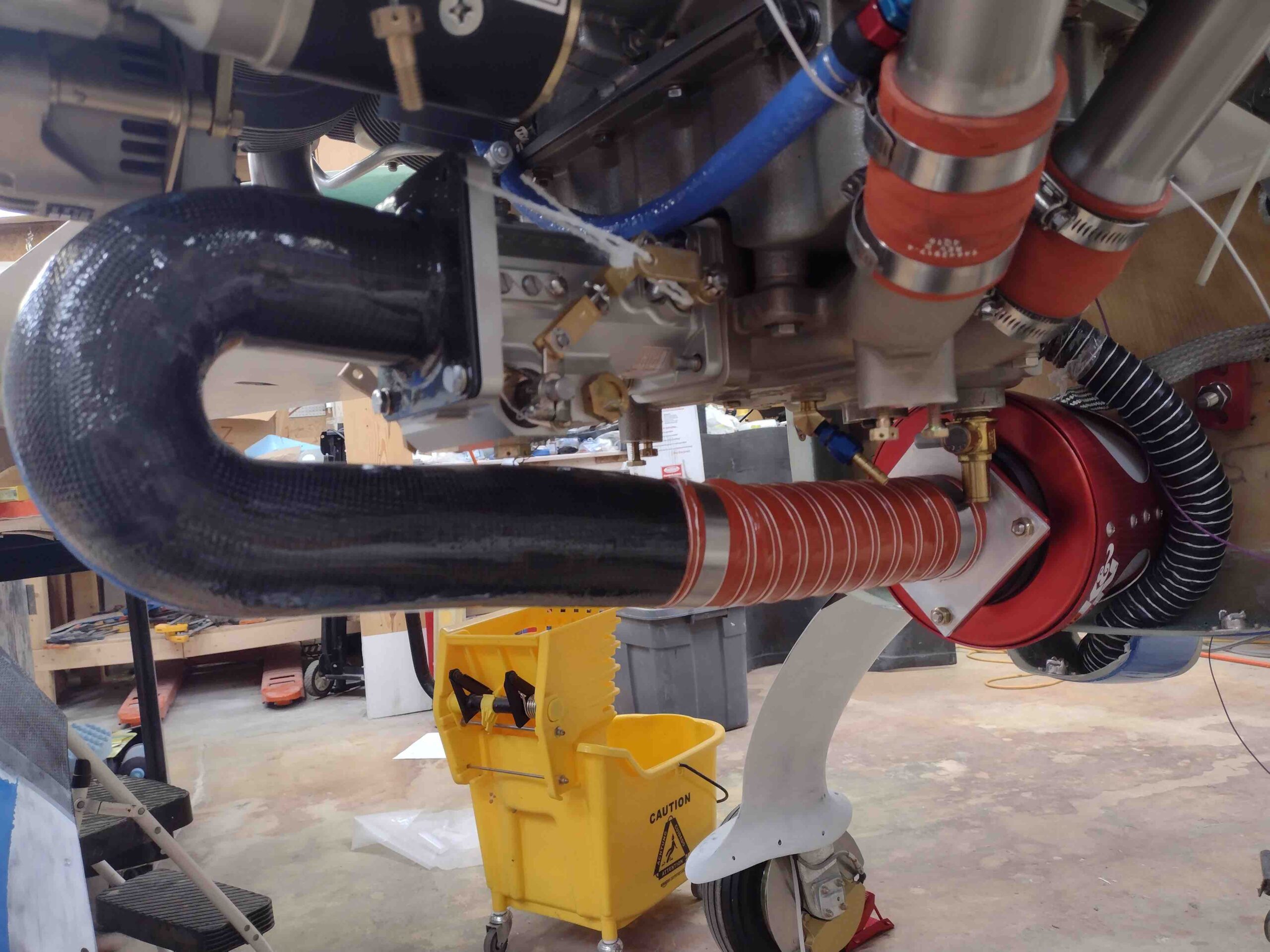
Another couple shots of the installed segment of the SCEET tubing between the RAM air can and the Fuel Injection Servo air induction tube.
I then grabbed a shot to show the alignment between the air induction tube and the RAM air can.
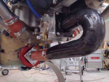
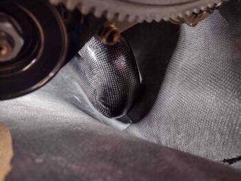
I then installed the lower cowling to check the clearance between the Fuel Injection Servo air induction tube and lower cowling. Because of the thicker tube wall than expected and fairly thick clear coat my clearance is a bit less than I had reached earlier… just under 1/4″. Obviously not as much as I’d want, but again I’ll take what I can.
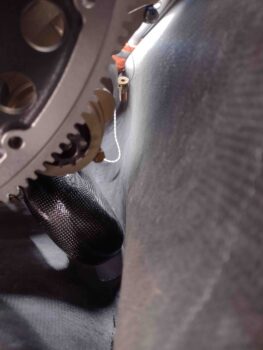
I’ll also note that with my dialing in a straight shot between the air induction tube and the RAM air can, the air induction tube sits slightly to the right of center… which means it’s a tad closer to the right side cowling wall.
It’s not untenable, but it is something I’ll be watching… here’s one last shot of the just installed air induction tube.
Tomorrow I’ll be pressing forward with finalizing the air induction system configuration. I’ll also be pressing forward with other engine components installs.