
Today I finally knocked out another big milestone on this airplane build: I’ve completed the major glassing (ok, with carbon fiber) and construction of the Fuel Injection Servo air induction tube.
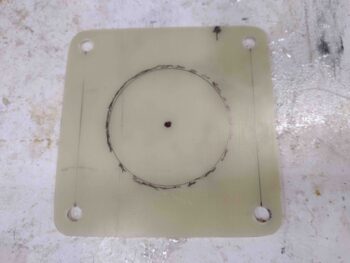
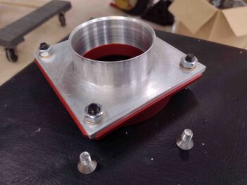
I started off by marking the 1/16″ thick G10 mounting plate while it was still test mounted onto the FI servo so that I could outline the inlet hole on the servo. The inlet on the FI servo is about 2.3″ wide while I measured the ID of the air induction tube at just under that.
Here we have my original marking with a 2.25″ diameter circle drawn inside of that from a template.
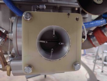
I then used a 2.25″ hole saw to cut the hole out, and after cleaning it up I then test fitted it back onto the FI servo. I don’t remember if I’ve covered it or not, but you may wonder why I never install the top right bolt… it’s because there is a plastic zip tie that runs through that hole that secures the throttle lever arm. Why don’t I cut it? Because according to Alan at Precision Airmotive, the fuel acts as a lubricant to the internal parts and actuating the levers with no fuel can create friction and internal debris in the servo… so now you know!
After an initial center alignment, I then duct taped the G10 mounting plate to the air induction tube on the inside corner. I then mounted the assembly to align the mounting bracket with the induction tube (and the tube to the RAM air can) before laying up all the carbon fiber.
My initial alignment wasn’t too far off, but I did need to move it a solid Sharpie line width counter clockwise (bottom tube part to right).
With the G10 mounting bracket in place where it needed to be to have the induction tube situated correctly, I then whipped up some 5-min glue and dabbed some into place at the junction of the mounting plate and induction tube… in 4 spots.
After the 5-min glue cured I spent a good 45 minutes cutting out carbon fiber pieces for a total of 5 separate layers of carbon fiber. Some layers had 4 pieces, some had 2 while the final layer I planned to have only one ply of carbon fiber.
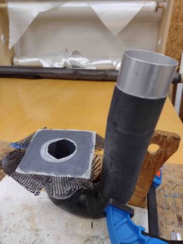
I then whipped up some epoxy and some flox. I added a flox fillet around the corner junction of the mounting plate and induction tube before laying up the first layer of carbon fiber, which was actually 4 separate pieces (overlapping at the corners). By the time I got to my 3rd layer I realized that with the overlaps —which I had attempted be in different spots with each layer— I was getting a lot more than a single ply per layer. In fact, with the overlaps I was getting close to one extra ply of carbon fiber per every 2 layers I laid up.
With this being the case, I decided to forgo the final one-ply layer and stop at 4 layers… again, very close I observed to around 6 plies of carbon fiber. I think that will do the trick! I then of course peel plied the layup and trimmed the excess carbon fiber at the edges. I then let it cure (Yep, I again used fast hardener).
While the external layup of the air induction tube mounting flange cured, I then investigated the front side of the RAM air can mounting flange. There’s very little clearance with the rubber mount that it seats into, so I figured there had to be countersunk screws for securing whatever mounting bracket goes onto it… in my case the SCEET mounting adapter.
In fact, the RAM air can even came with 1/4″ CS screws (silver, in front) for this purpose. Unfortunately these screws were simply way too short for the job. So I ran to Lowe’s to grab some test screws and also did a quick round of food shopping. When I returned I mounted up my SCEET mounting bracket to the RAM air can mounting plate.
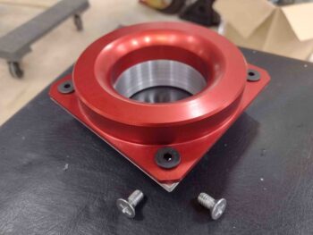
Here it is from the other side. This tells me that even with a gasket in place these 3/4″ screws will be the right length.
A little while later I determined that the carbon fiber securing the G10 mounting flange to the air induction tube was cured and ready for trimming with the Fein saw. After I trimmed off the excess carbon fiber, I then re-drilled the 4 corner 1/4″ mounting holes.
I left the peel ply in place for the time being since I didn’t want any epoxy to seep down from the mounting flange front side layup and gunking stuff up.
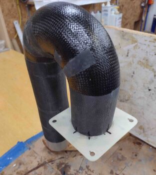
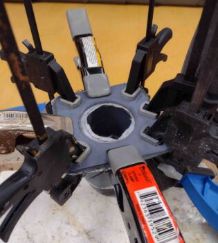
Curiosity got the best of me and I had to test mount the new and improved air induction tube, replete with its own mounting bracket!
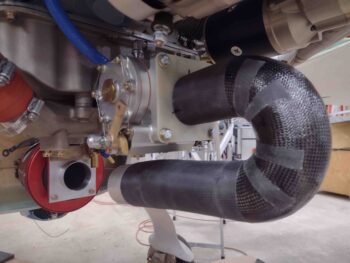
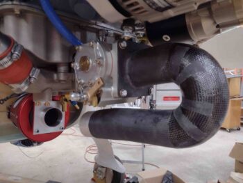
Here we have a couple more angled shots of the air induction tube mounted to the Fuel Injection Servo via the glassed in place mounting flange.
It was now time to finish this puppy! I used my Dremel Tool with a sanding drum to carefully clean up the edges of the G10 mounting flange hole and also slightly reduce down the first 1.5″ of the wall inside the hole. I also added a radius at the edge of the mounting plate going into the tube.
Once again I found myself in the realm of compromises… I wanted and initially had planned to lay up 2 plies of carbon fiber on the front face of the mounting flange, but realized that I risked adding just a bit too much thickness to the interior sidewall —thus reducing the tube ID— and, moreover, I would then have to contend with at least 2 plies (actually 4 since I had to cut the plies at least in half to get down into the tube) on the fairly sharp radius at the edge of the mounting flange hole going into the tube.
After pondering it a bit, I ascertained that I had essentially 6 plies of carbon fiber on the outside of the flange with 4 bolts securing both those 6 plies and the G10 flange to the FI servo… this mitigated in my mind the importance of these 2 plies and I decided that one ply would do just fine. Yes, the airflow —which this is all about— won out while I still of course think I have all the strength and robustness I need to secure the air induction tube to the FI servo.
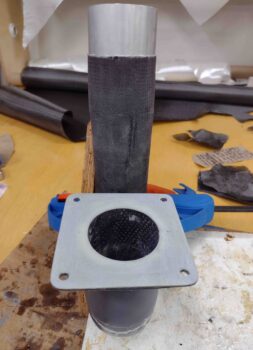
With that, I used 2 pieces of carbon fiber to lay down a single ply covering the entire front face of the mounting flange and into the induction tube about 1.5″ deep.
After peel plying both the internal tube carbon fiber and front face of the mounting flange, I then trimmed the carbon fiber around the edges. I then taped up one side of the original 3D printed mounting flange mockups with clear packing tape and clamped it in place to compress the carbon fiber on the front face of the actual mounting flange.
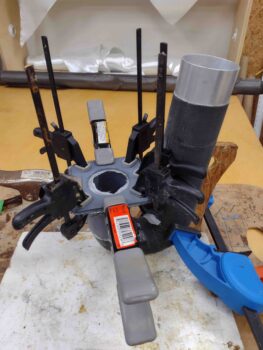
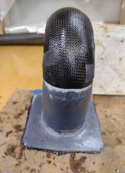
Here’s a closer shot of the mounting flange front face peel plied carbon fiber layup being compressed in place with a clamped 3D printed mockup.
Once again I used MGS with fast hardener so about 3+ hours later I was able to remove the clamps, re-drill the mounting holes, razor trim the overhanging carbon fiber, pull the peel ply and clean up the layup.
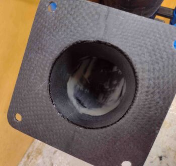
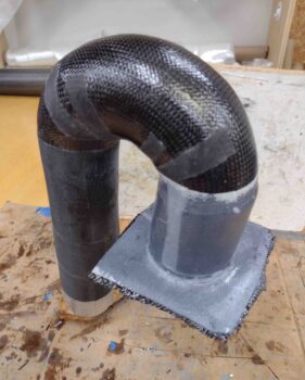
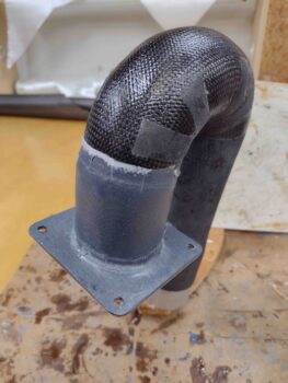
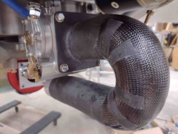
Here’s a couple of other shots at different angles of the air induction tube mounting bracket and tube carbon fiber layup.
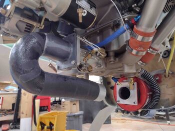
I also pulled the peel ply and cleaned up the exterior mounting flange layup I did earlier. I then mounted the finished air induction tube onto the Fuel Injection Servo. Not bad!
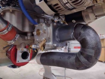
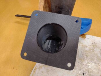
Here’s a closer shot of the mounting flange/bracket.
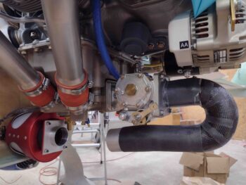
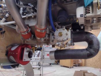
And a shot of it all more from the side…. If the angle looks a bit odd between the RAM air can and the 6061 SCEET adapter on the front of the air induction tube that’s because it is. Optimally the air induction tube would swoop down and then curve up slightly to have the 6061 tube staring directly at the RAM air can SCEET adapter.
The issue once again is the clearance with the bottom cowling, which required me to keep the air induction tube as high up as possible. At the very front I snuck a 5º down curve (3º would have probably been best) which will produce a slight curve in the SCEET tubing, but the angles match much better than just keeping the front of the air induction tube straight.
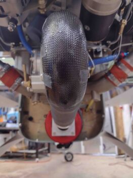
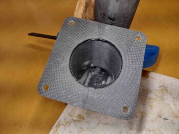
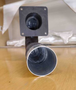
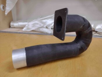
I then grabbed some free standing shots of the finished Fuel Injection Servo air induction tube.

This shot shows down the gullet a little bit . . .
And one last shot… again, at some point I’ll hit the carbon fiber with some type of epoxy clear coat to make the carbon fiber sizzle and pop (even though it’s in the engine compartment… need bragging rights!).
As an fyi, this induction tube presently weighs about 3/4 lbs. Which is actually 1/10th of a pound lighter than just ONE of my original 90º aluminum bolt-in elbows. So not too shabby on the weight either.
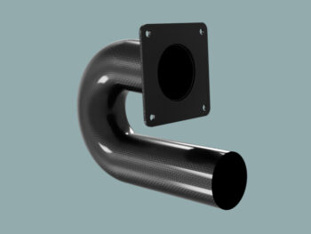
As a reminder, here is my original rendered CAD model of this thing… not a too far off outcome if I do say so myself.
It’s been a super long day and a super long evening… and with that folks, I’m calling it a night!