
Well, I’m back from all my holiday travels. Time to dispense with fun and frivolity, and get back to work on the bird!
As I was cleaning up the open browser tabs on my computer, I ran across a stainless steel bung that I had assessed for the compression style EGT probes. It was a bit more expensive than the ones I purchased, and is a bit simpler in that it eliminates a component by combining the compression fitting with the threaded bung… essentially a compression fitting with a bung on one end for welding it to the exhaust pipe.
The vendor’s website thankfully included CAD drawings of their parts for sale, so I simply downloaded that and within minutes had 3D-printed a version of their EGT probe mounting compression fitting/bung (I didn’t 3D print the internal sleeve or cap).
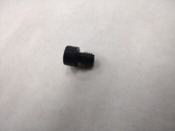
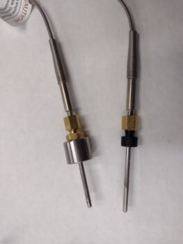
This new EGT probe stainless steel mounting compression fitting/bung (right in pic) is considerably smaller than the compression fitting + stainless steel mounting bung combo that I currently have on hand.
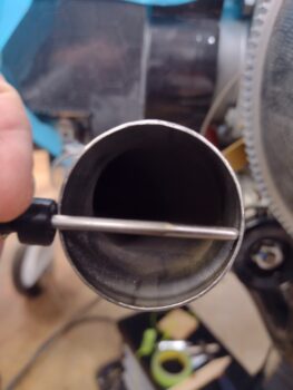
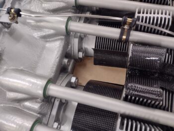
One critical factor that I needed to check with both these EGT probe mounting bungs is the positional depth of the EGT probe inside the exhaust pipe. Although there is a little wiggle room, I pretty much want the compression style EGT probe inserted fully into the compression fitting/bung… and this issue revealed itself while testing out the possible use of this new combined compression fitting/bung, as the EGT probe ends up nearly touching the opposite wall of the exhaust pipe (pic 1). While my current compression fitting + mounting bung has the EGT probe positioned more in the center of the exhaust pipe.
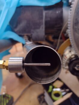
Clearly this new combined EGT probe compression fitting/mounting bung was too small to allow for good internal exhaust pipe positioning of the EGT probe. Thus my test was successful since it showed me that I simply need to press forward with what I have on hand, albeit still throw these rather chunky stainless steel bungs on the lathe for some needed weight reduction diameter wise, but leaving the height as is.
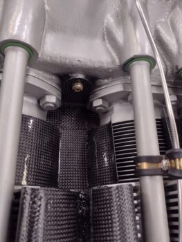
I then got busy with the somewhat tedious process of fine tuning the fit of my cardboard template for the cross shaped right side inboard inter-cylinder baffle. After a good half hour of iterative fitting machinations, I finally had it in place with minimal daylight showing around its perimeter.
I then transferred the final shape of the template to the actual CF right cross shaped inboard inter-cylinder baffle and trimmed it up. I then glued the CF cross shaped baffle into place and let it set with some slight weight on it for a couple of hours.
While the initial cure took place on the right side cross shaped baffle, I trimmed off the curved lower cylinder baffle wraps from the forward VAN’s aluminum wall baffle segments… since with the CF inner baffles in place these were now redundant (sorry, no pics yet).
I then removed the weight from the curing right side cross shaped CF inter-cylinder baffle —tacked at this point— and installed/glued in place the 90° right-angled tab that secures the cross shaped inter-cylinder baffle in place (since it clearly has a good amount of upward traveling air to retain). I trimmed the top side of this right-angled tab in a pleasing curved shape and also added some Loctite to the screw before threading it into place.
With my “practice run” of getting the top inboard inter-cylinder baffle installed on the right side of the engine knocked out, tomorrow I’ll tackle the left side… which will be a bit more challenging given I have to account for the fuel line that travels from the fuel spider to the fuel injection servo.
Inching forward!