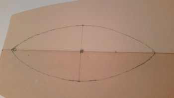
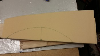
I started off today by marking up the area on the floor pans that gets dished out. At this point, it was just for planning purposes since my main goal for today was to figure out the location to mount the rudder/brake pedals. Once I figured out where the rudder pedals would go, I could then finish dishing out the floor pans and prep them for install.
I also did the final mark up on the side panels that go between F22 & Napster.
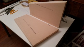
I then sanded the aft end of the floor pans to a 10° angle.
And cut & trimmed the left side panel (not pictured). Although I widened my fuselage 1.4″ at the front seat back, my F22 is pretty much standard size. So cutting the side panel to the listed dimensions should have gotten it really close to fit into the current F22-NG30-Napster configuration. It was close on the aft side and ok on the bottom edge, but the front was pretty far off. The angle called for was just too severe as compared to the actual F1-3 Napster aft lean.
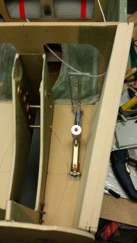
After messing around with the side wall for a while, and finally getting it into an acceptable shape to fit into place, I started mocking up the rudder pedals. I spent a good hour doing research: comparing my buddies’ build sites, re-checking the plans, etc. as I tweaked the final location of the pedals.
I also climbed into the fuselage and tried out my feet location to double check as well. Now, a couple things of note are that my rudder pedals are adjustable, but of course that’s only for fore & aft. Also, the rudder pedal plans specifically state to keep the pedal 1-1/4″ away from the sidewall. Part of the reason for me doing so much cross-checking in my research is that this 1-1/4″ clearance with the sidewall is a tall order in such a small space as the nose, especially since with the Davenport nose the sidewalls stay rather thick. The bottom line is that as long as I have a good clearance with the sidewall, the 1-1/4″ clearance requirement is just not happening.
The main reason for ditching this lofty clearance requirement is that one of the really nice features of the Long-EZ is to remove your feet from the pedals while in cruise flight and resting them adjacent to the pedals, wherever they happen to be mounted (some folks mount them on the inboard side vs the outboard plans side). Clearly, with the pedal mounted more towards the center of the foot/leg opening in F22, that diminishes the comfort of the pilot (me!) during flight. So again, I’m chucking the 1-1/4″ clearance for a more reasonable one considering the tight quarters in the nose.
BTW, if you look in the pic below you can barely make out the gap in the junction between the front of the sidewall foam & the F1-3 bulkhead, aka Napster.
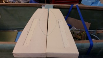
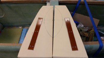
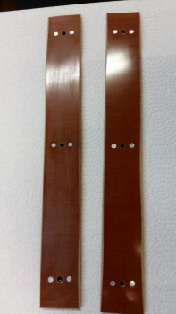
With compromises on side clearances made with the rudder pedals, and thus the mounting location on the floor pans pinpointed, I marked around the perimeter of each phenolic pedal base (that comes with 3 x K1000-3 AN3- nutplates pre-installed…nice!). I then used my router to remove about 3/32″ of foam so that each base would lie perfectly flat with the top of the base level with the surface of the foam, allowing a minor clearance for application of micro as well.
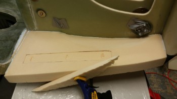
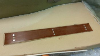
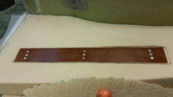
Here are the pedal bases fitted in the their mounting recesses in the foam.
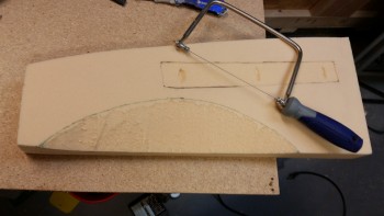
As I mentioned at the start of this post, with the location of my pedal bases set & confirmed, I could now dish out the inboard side of each floor pan. I started by removing about 90% of the material with a coping saw.
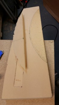
I then used my half-moon Perma-Grit tool to remove the rest of the material and sand the dished out area to its final shape.
After the inboard edges were dished out, I then expanded the depressions in the foam for the K1000-3 nutplates just a tad to provide the proper clearance when the rudder pedal base plates are micro’d into place in the floor pans.
Since it was raining outside, I had to reorganize the shop a bit & play musical chairs with my motorcycle to get access to my glass cutting table. Once table access was “granted,” I then cut out 2 pieces of BID for each floor pan and 3 pieces of BID for each sidewall piece.
While cutting the BID, I used up the final bit of glass on the roll mounted in my cutting table. I loaded up another roll, and have to say this time it felt really good because I knew that this would be the last roll of BID that I will use for this project!
Now, the plans call for 2 pieces of BID for each sidewall piece, so why am I adding a third piece? Because I’m breaking the rules. The plans for the Davenport nose say specifically NOT to dish out the side walls, but having nearly 2″ thick Divinycell side walls for an 11″ nose extension is a bit of overkill in my opinion. Since the foam is so thick, when matching up the sidewall with the opening in F22, the plans do call out for dishing out the side wall to ensure a smooth transition with inboard edge of the F22 sidewall.
Thus, my plan is to leave the bottom of the sidewall the normal width for this install, but in the area above where the sidewall gets dished out, I narrowed the sidewall foam to 1.1″. I figure if the Ronenburg extended nose and others call for 0.8″ thick sidewalls using blue wing foam, than 1.1″ thick Divinycell on the top half of the sidewall with an extra ply of BID will be plenty strong.
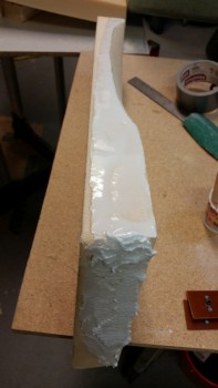
With everything prepped on the floor pans, after one final fitting check, I whipped up some micro and slathered it on the surface areas that would mate with the existing nose components. Since the 10° called out for in the plans is just a tad bit too severe, I needed to fill a about 0.050″ gap in-between the floor pan and the F22 bottom front, so I mixed in some flox to create some flocro to apply to the back edge of the floor pan. That explains the slightly different consistency & color you see between the edge micro and the back flocro that is visible in the pic below.
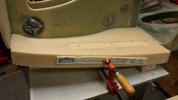
I mounted the right floor pan first & then clamped it into place.
I then micro’d up the edges of the left floor pan and installed it. When I pulled the clamp off of the right floor pan to install the left one, there was very slight gap that was created between the NG30 and the floor pan. Although I had planned on glassing the floor pans this evening, it got me to think that I wanted the seams as tight as possible, so I simply re-clamped both floor pans together and decided to let it all cure overnight.
I then got to work sanding the phenolic rudder pedal bases with 100 grit sandpaper. You can see below that the left base is sanded while the right one isn’t.
I then filled the K1000-3 nutplate bolt holes with saran wrap and did a final test fit for each rudder pedal base into the floor pan foam. I’ll micro in the pedal base plates just prior to glassing the floor pans.
Tomorrow will be a rather busy day work-wise, etc. but I do intend on getting the floor pans glassed as a minimum.

What kind of foam are you using on the nose?
H45 Divinycell. I know, it looks like that urethane crap. For whatever reason I got yellow PVC foam instead of the standard blue/bluish green. I was going to finish it and tell you that it was urethane as a joke, but since you asked me on the blog I don’t want to confuse anyone!
Cheers,
Wade