
Well, between the still quite chilly weather, a good day and a half storm (causing a bunch of tornados inland that killed some folks), helping a friend using the trailer and knocking out a few other household tasks, I haven’t been as focused on the build over the past week as I want to be.
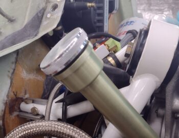
I’ll start off with reporting some good news. I received the billet aluminum (or so it was advertised… it IS aluminum) threaded dipstick cap. I immediately took it out to the shop and checked the fit: spot on! It threaded in nice and smooth.
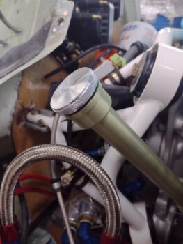
Here is the top face of the cap. I’ll be drilling a 3/16″ hole in the center of this cap face to mount the dipstick rod.
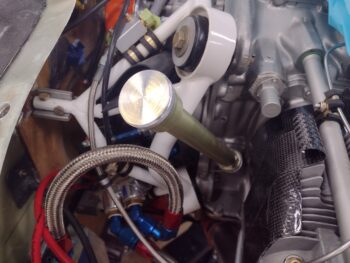
This dipstick cap has an o-ring seal just like the Lycoming ones. But unlike the Lycoming/Superior dipstick caps, this one is LOW profile to avoid clearance issues with the top cowling.
In other news:
I’ve also been doing some research to FINALLY finalize my lathe CNC conversion to allow me to get some parts made and tweaked (e.g. the EGT probe threaded mounting bungs).
I’ve had a kit from the Little Machine Shop in my possession for almost a year now that will convert my lathe to allow for the CNC system to control the lathe’s spindle speed and direction. To do this, I have to add another board into the mix and tie it in to the existing electronics via a cable.
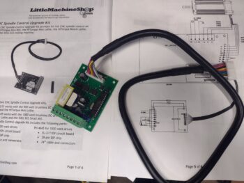
The first task in converting my lathe’s control board to allow adding in the new CNC control board was to swap out an integrated circuit (IC) chip one of the existing boards. The removed original chip is in the Styrofoam block resting on the cables.
In addition, I needed to find a home for the added CNC control circuit board inside the lathe’s electronics housing. The problem is that there is simply no room for this new board with how things are configured inside the housing.
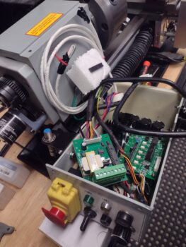
After doing a good bit of measuring and assessing the setup, I decided to mount the new CNC control board outside of the electronics housing and simply run the cable in from outside. It will be mounted to the left outside wall of the electronics housing under the left end spindle cover.
To minimize any dust or debris from dirtying up the new CNC control board, I designed up a protective box in Fusion 360 CAD.
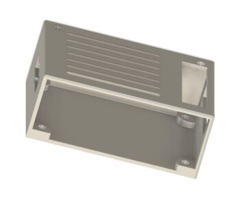
I kicked off the 3+ hour 3D print on this new protective box, but about halfway through the ABS/polycarbonate filament I was using didn’t do well at all in printing out the box, so I switched to a standard ABS and restarted the print. We’ll see how it turns out in the morning.
Since the weather over the next 6 weeks will most likely remain too cold for me to the major micro finishing on the remainder of the plane (unless we get a multiple day warm spell), I’m going to focus on all the other tasks —including cutting and mounting the firewall— that I can do until I can get to micro finishing. Up next is still finishing the aft lower aluminum engine baffles.