
After departing NC on this last trip to clear out my #3 storage unit and consolidate nearly all the airplane build stuff in the hangar, I headed up to Virginia Beach to spend a couple of days with Marco and Gina.
While at Marco’s, I updated my Instrument Panel CAD diagram with all the dimensions I had taken off the actual panel while down in NC. With Marco’s help, I then shared the CAD file to a shared online folder and he was then able to convert it into CAM to be drawn out on his plasma cutting table with a Sharpie onto cardboard.
This may seem like some underutilization of a fairly expensive plasma cutter to merely use it as a plotter, but not only did it test & confirm some limit capabilities of Marco’s plasma cutting table (better than we initially thought), but obviously it will allow me to cut out the cardboard panel, test it in the actual airplane, and then make any required tweaks if need be before we do an actual plasma cutout of the panel with actual expensive aluminum.
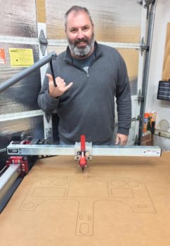
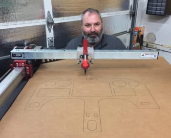
In fact, the pics of the crazy bearded guy below (me!) is with plotted panel version #1, which afterwards I realized that I had forgotten to update some dimensions I had gathered relating to the panel’s upper corner longeron notches . . .
Although I’d like to say it was fairly easy to update the CAD file to redraw the dimensions on the panel longeron notches –and subsequently the top panel contour– it actually did take a bit of drama-filled machinations to get it done. But, with Marco’s help I learned a few new tricks regarding Fusion 360 and was able to update the panel drawing to the correct dimensions.
We then embarked on plotting out Instrument Panel version #2 on Marco’s plasma cutter with no hiccups.
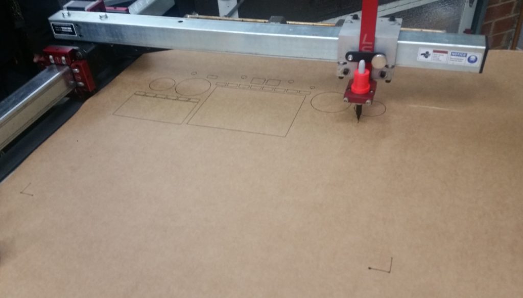
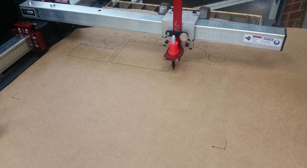
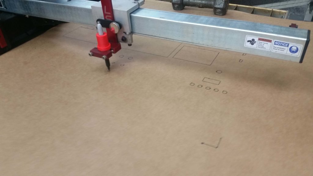
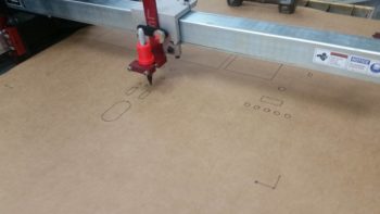
In fact, I took a short video of the last little bit of the panel plotting effort on the Plasma Cutting table. We didn’t film the entire event since to draw the separate circles and rectangles in the panel we had to lift the Sharpie up slightly in its holder (which Marco cleverly designed and 3D printed) after each drawn component to allow the assembly to relocate to the new spot that the next component would be drawn, then slide the Sharpie down in contact with the cardboard.
This pen lift/drop cycle is shown in the video, as is the entire drawing of the Instrument Panel perimeter.
After the instrument panel plotting was done on Marco’s plasma cutting table, I then labeled the components on the cardboard to grab this shot here. Most of the larger component holes will get cut out, which I’ll show in a subsequent blog post.
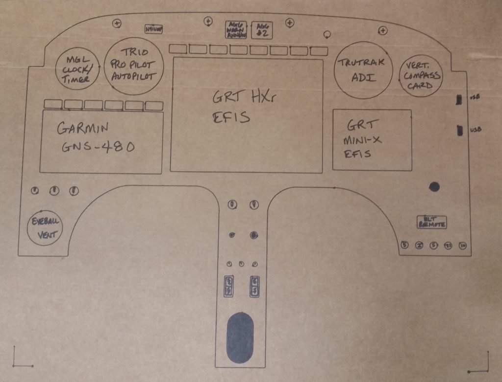
I’m extremely pleased with how the cardboard panel mockup came out, and am excited about dialing in the panel CAD drawing to enable Marco and I to plasma cut my panel out of a piece of aluminum. I will say that Marco and I (and a few others) are discussing the pros and cons of 2024 vs 6061 and what thickness the panel should be (0.063″ to 0.090″).