
Over the last week, save going out on the boat and fireworks watching for July 4th, I’ve been scurrying about cleaning up the shop and getting my build priorities in order. That being said, this blog post covers the last few days of my build shenanigans.
One task, that in part led me down the 3D printing rabbit hole for a good month plus (combined with throwing my back out!) was the issue with the too-short oil dipstick/filler tube. Well, after some height confirmation and testing with the upper cowling on —and a bunch of research— I’m happy to report that I pulled the trigger on a new oil dipstick & filler tube from Aircraft Specialties Services.
You may note from the pics below that this doesn’t look like Grandpa’s ol’ plastic Lycoming oil tube, and that’s because it is most definitely not. The 10.57″ Lycoming oil level tube is p/n 75767, whereas this (again, after a good bit of research) is the Superior Air Parts anodized aluminum oil tube, p/n SL75767. Note the lack of protrusions in the middle area that lends this tube the ability to stay as far off as possible from the engine mount tube. Hopefully, this tube will put this issue to bed!


With the oil dipstick/filler/level tube ordered and on its way, I then started back on the engine to get its position situated and finalized. Yes, in my fast and loose style of living dangerously, I didn’t have the very forward bolts of my engine mount extrusions installed yet (shown below) to accommodate working all the engine electrical components in the GIB headrest.
Thus, to ensure full clamping pressure of the forward engine extrusion bolts, I lifted the engine up slightly to relieve any downward pressure on the engine extrusions (aft) that might lift the engine extrusions upward on forward side.

A quick aside before I continue on with the forward engine extrusion bolts.
** Note the two left exhaust pipes showing in the above pic. Although I trimmed them to minimize their overall height, they still need to be tilted up at the aft end to eliminate their closeness to the inside surface of the bottom cowling. Once I get the engine bottom mounts finalized (they’re currently tight but not torqued fully to spec), I’ll assess and query Clinton at Custom Aircraft Parts about bending the outboard/forward exhaust pipe and cutting rewelding the inboard/aft exhaust pipe. This should eliminate/greatly minimize any cowling rework. Note that the left side exhaust pipes are close, but acceptable enough that they don’t need any rework (bottom line: this is a tight cowling!) **
Now, back to the forward engine extrusion bolts. First, in the pic below note immediately above the seatbelt strap on the right side of the pic is a red electrical FastOn terminal. Immediately behind that is the 90° aluminum extrusion that traverses the bottom of the GIB headrest engine electronics bay from one side to the other, and secures the bottom sides of the respective components… I installed this first since after the seatbelt bar was installed it would have been much more difficult to install this extrusion.
As you can see, the forward engine extrusion bolts secure the outboard ends of the strap bar for the GIB upper seatbelts. Why this bar versus the plans method of attaching the upper seatbelt straps for the GIB? Have you ever ridden a hairy roller coaster at an amusement park? They pull the padded bar down over your shoulders so that your head barely fits through it, not out on edges of your shoulders. Because not only does is not hold as well on the edges of your shoulders, it’s uncomfortable!
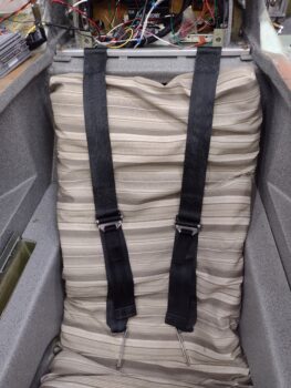
If you look a bit closer you can see two screws, each about an inch inboard of each strap. These inboard stops essentially provides a “slot” on each side to move the straps back and forth, with the furthest outboard position still about inch inboard from the plans position. These screw points also secure the bar from flexing or bending in the middle for better rigidity.
I’ll note for clarity’s sake that although I’ve been using the term “bar” here, that it is actually a 6061 square tube. Moreover, there is an alodined 2024 insert with a 0.25″ thru-hole mounted inside each end of the tube to ensure the AN4 bolt clamping pressure doesn’t collapse the square tube.
After installing the forward engine extrusion bolts and GIB upper seatbelt strap bar, I then lowered the engine hoist to let the engine settle back into its normal resting state. I then rolled the engine hoist out of the way and removed the bottom cowling.
Looking over everything on the bottom of the engine, I realized that I hadn’t yet gotten around to tapping the bolt threads for 2 of the bolts that need to go into the carbon fiber air induction tube flange to secure it to the fuel injection servo’s inlet face. The issue is that the unthreaded shank of each bolt doesn’t allow it to be threaded in all the way. With these bolt threads tapped, all the hardware is ready to go to secure the air induction tube to the fuel injection servo.

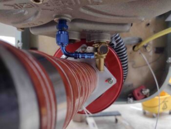
Finally, I took another hard look at the sniffle valve. I discuss this in one of my latest videos where after I tweaked the SCEET tubing to remove any internal bumps and wrinkles, the end result is that it also removed the slight downward curve (dip) of the SCEET tubing. With the SCEET tubing now a straighter line from point a (RAM air can) to point b (air induction tube) the 90° sniffle valve fitting is a bit too close for comfort to the SCEET tubing [this older pic shows the sniffle valve I’m talking about with the SCEET in the previous “dipped” configuration].
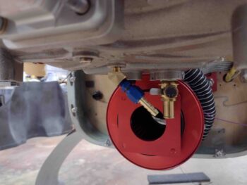
To remedy this, I’m going back to my original sniffle valve configuration where I first have a 45° street elbow installed in the bottom of the cold air plenum followed by the actual sniffle valve (see pic below). This 45° angle should provide immediate clearance between the sniffle valve and the SCEET tubing below it.
Since I stole the only 45° street elbow I had on hand for the MAP block install, I fired off an order for another couple elbows.
Pressing forward!