
Today was one of those days where I didn’t seem to get a lot actually done, but I got a lot of stuff figured out . . . which is also important.
I started off by pulling the peel ply from last night’s layup, razor trimming the layups and then cleaned them up. I have to say they all came up pretty good. Since I added glass to an area that I had been trimming a lot for clearance, I then test fitted it to ensure I still had the proper clearance. It was a little tighter, but it still fit fine. I think if I sand it down well it should fit very nicely.
I then worked a fair amount more on the parking brake. I’m sure this may be the bane of my build for many builders/readers of this blog, but it’s one of those things to me that I should work now since I have access, and once the airplane is done it will be a nice extra to have.
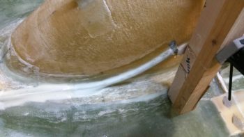
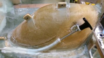
I took another 20 minutes to carve out about an inch more of the 1/4″ Nylaflow conduit buried under glass and micro to free it up so I could get the slope angle right from the conduit to the parking brake T-handle bracket. Once I got it right, I then 1-minute glued it into place, clamped it, and let it cure a good 10 min under a heat lamp while I prepped for the 1 BID layup.
I cleaned up the excess glue and then filled in the gaps around the now exposed –and trimmed– 1/4″ Nylaflow and the nose wheel cover (NB) with thick micro. I then laid up 1 ply of BID over top of it, and set up a heat lamp on the layup. I didn’t bother peel plying this layup (I know…crazy!)
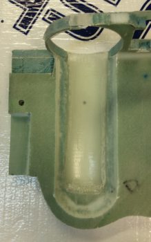
Here’s a shot a bit later when it was cured. I didn’t get an exact alignment between the Nylaflow conduit and the parking brake handle assembly, but it’s close enough and causes zero operational issues.
Here’s yet another shot of the final install on the parking brake T-handle. Obviously, I like this location, and it works well for me.
I then spent about half an hour using a piece of cardboard to make up a template for my parking brake engagement panel LED indicator lever switch mounting plate. This will mount over 3 of the 4 screws that were used to mount the NG8 plates to the inside of the left NG30 plate, at the nose wheel pivot mount.
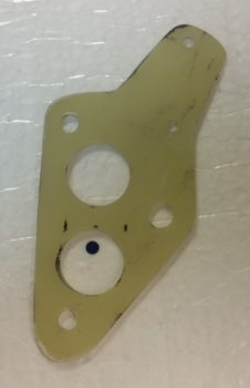
I then transferred the dialed-in template to a 1/16″ thick G10 plate and cut it out. I then slowly drilled the holes one by one to allow it to fit onto the exposed NG8 screws, and then once I got the upper 4-40 switch holes drilled (small holes, upper right), I then drilled 2 x 5/8″ lightening holes on the lower side.
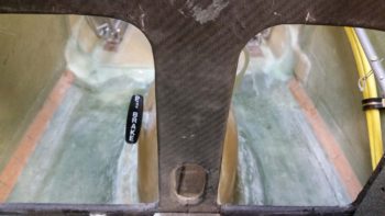
I then labeled the switch. I also verified, cut, terminated and labeled the wiring running to/from the parking brake engagement panel LED indicator lever switch. I then mounted the bracket and switch combo and verified the switch functioning and angle… it all looked good so far.
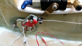
Below is the switch in the closed, parking brake and LED indicator OFF position.
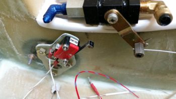
In this shot, the parking brake has been engaged, which opens the switch and closes the circuit, turning the LED indicator ON.
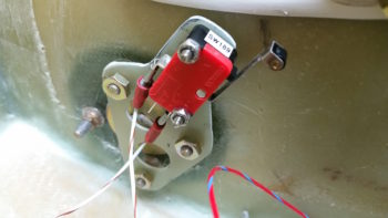
Finally, here’s a closeup of the parking brake engagement panel LED indicator lever switch and its mounting bracket.
During the process of wiring up the parking brake engagement panel LED indicator lever switch, I also verified my panel LED indicator lights Push-to-Test button operation, circuit design and configuration… and the panel indicator lights dimmer function as well. Tomorrow I have to help some friends out with some household maintenance stuff, but I should be able to continue on with my in-cockpit configuration quest.