
I started off today assessing the configuration of all the hell hole components and the wires in, around and through the hell hole. I did some research on drilling into the CS Spar, knowing that the Spar Caps were sacrosanct, but what about the other areas? I’ll touch on this later in this post.
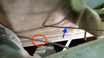
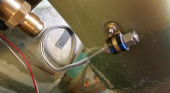
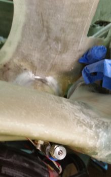
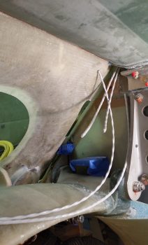
I then started my shop tasks today with a small repair. Yes, hard to believe that any of the 1/8″ aluminum brake line tubing coiled up in the hell hole since 2012 would ever get a ding or scrape on it . . . well, folks, the unthinkable happened! On my left brake line, about 6″ where it exits the lower fuselage, the tubing had a visible dent/crimp in it (circled in red in pic below).
My goal this morning was to either extricate the dent/crimp and repair the line –without destroying or mangling it– so that it would function as designed, or go with the nuclear option if need be: cut the line at this point and tie in the brake line coming from the wheel farther forward than I had planned.
By my calculations I was dealing with a 0.075″ diameter hole, and I measured a piece of hanger wire that I’d be using at 0.069″ …. Hmmm, seams like it should work (blue arrow in pic below). I filed the tip smooth and hit it with Acetone to clean it. But it proved just a tad too thick. Plus, it wasn’t as arrow straight as I would prefer.
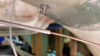
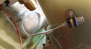
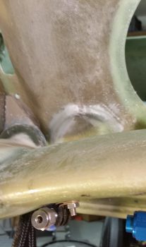
After pondering a bit, Voila! I found the solution, pressing a perfectly straight and slightly narrower TIG welding rod into service. I marked a point on the rod that was past the offending dent in the line, and slowing worked the rod, and aluminum tube, to get the rod though the tube and remove the pinch in the line.
Here you can see I’ve reached my mark, denoting that the 1/16″ welding rod is clearly past the offending pinch in the brake line. I then worked the both the welding rod and tube for a good 10-15 min longer just to ensure that the dented section was as opened back up as close as possible to full diameter.
I wanted to institute some service loops for the brake lines and had some initial thoughts about using Adel clamps or some other means to keep the tubes in place. Not only did I want to keep the aluminum brake line tubes themselves clean in the event I may need to use them for any reason in the future, but I definitely wanted to protect them as well, especially since I do plan on jamming stuff into the hell hole for storage during flights.
I tried Nylaflow but the resulting loops against the lower aft side of the GIB seat back bulkhead proved too tight for Nylaflow. I even tried working the Nylaflow into a nice loop before placing it on the brake line, but it just kinked on me when the radius got too tight. Looking around the only thing I had on hand was the clear tubing I was using for the engine dehydrator, so I stole a couple of lengths off the line and pressed them into service.
Since the tubing will be out of the sun and under what we Canardians typically do in situations like this –bury it micro and throw a couple plies of BID on top!– I wasn’t overly concerned that it’s not “aircraft grade.”
After the protective clear tubing was in place over both brake lines, I then cleaned up the ends of aluminum tubing and temp mounted them in their respective reducer fittings. I then mounted the reducer fittings in their respective Adel clamps. That gave me a starting point to finalize the size and configuration of my brake service loops, which I then taped in place.
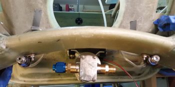
Here are Before & After pics of the right side brake line set in place and then with the service loop micro’d and glassed in place with 2-plies of BID . . . I used 2 plies to help protect the brake line against any untoward pinching. Obviously brakes are quite a useful thing in fast landing aircraft like Long-EZs.
And here are Before & After pics of the left side brake line set in place and then with the service loop micro’d and glassed in place.
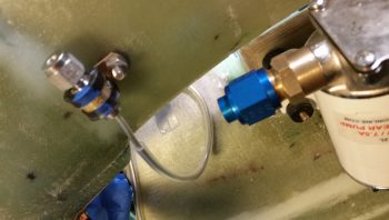
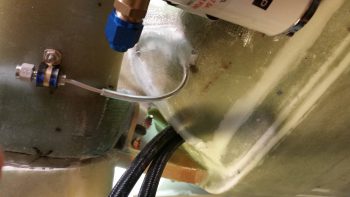
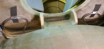
A different view of the right side brake line with the service loop micro’d and glassed in place.
Left side brake line with the service loop micro’d and glassed in place.
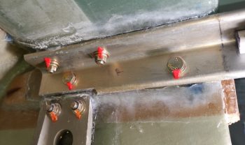
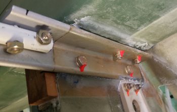
While the micro and BID layups cured on the brake line service loops, I took a few minutes to mark my lower engine mount extrusion bolt heads, nuts and washers with some orange torque seal.
I then set my sights on getting the wing NAV/Strobe and Wig-Wag lights wiring runs in the most unobtrusive, out-of-site way possible. As I mentioned at the start of this post, I had done a fair amount of research both in the plans, and online, in regards to drilling holes in the CS Spar. The results of my research was of course to stay away from the Spar Caps, no drilling through the shear web (which is actually common for the one hole required for the Autopilot roll servo, if used) and remain clear of the extrusion hard point areas.
I’m not sure exactly what #3 is all about since I have no plans on drilling INTO the hard points, but any viable hole for cable runs is going to be within 2″ of the hard points… and that is “in the area” in my book…. so of the 3 sacred “No-drill” rules I found, I’m apparently violating all the but the spar cap rule.
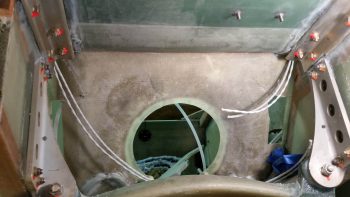
So, in probing around in my hell hole I discovered a spot up in each corner just aft of the CS Spar-GIB seat back intersection where there is sparse glass/flox. It’s actually the lower angled “bull nose” of the CS Spar and that is where I placed my bullseye for drilling a 1/4″ hole diagonally/aft on each side to run my wing lighting wires from hell hole to CS Spar (or vise versa). Here’s the result.
Might I say for my friends in the southern hemisphere: it worked a treat!
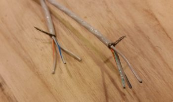
I then pulled the wiring out of the hell hole/CS Spar and took it upstairs for further processing (i.e. soldering). I then soldered the left and right CS Spar wing NAV/Strove light wiring together along with the shielded cable run to the light switch on the panel.
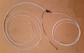
I know it’s fairly difficult to see the wires, but I looped them up over my kitchen light with both sides dangling down just to get an idea of how long the wiring harness is that we’re dealing with here. And this only gets out to the end of the CS Spar. The internal wiring that goes through the actual wings is yet to come!
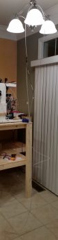
Here’s the completed wiring harness for the wingtip NAV/Strobe lights. It’s late so I stopped on this harness, but I will also have wing tip (or outer wing let’s say) mounted landing/taxiing/wig-wag lights as well, which I still need to make up that harness for. BTW, the left/right CS Spar portion of the wiring is on the left in the pic below, the black ground wire will tie into the “Forest of Tabs” in the hell hole, and the wire bundle on the right goes forward to the switch on the instrument panel.
Tomorrow I will continue with my Hell Hole shenanigans to the point I’m comfortable with closing up the major access to the Hell Hole by installing the Firewall.