
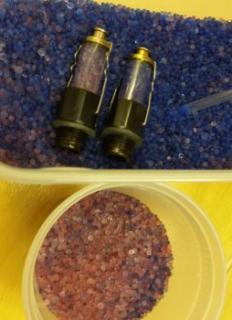
I feel like I have a cat now because I started off the day skimming the top layer of pink desiccant out of the engine dehydrator container (just like the proverbial kitty litter box). I also pulled initially 2, then 3, engine dehydrator plugs and swapped out their pinkish desiccant for nice deep, rich blue desiccant.
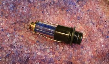
Here’s the third and last engine dehydrator plug in which I swapped the desiccant out. I placed it on the bed of pink desiccant that I was just getting ready to pop in the oven for an hour or two at 240° F. Not pictured are a half dozen desiccant bags I pulled out of the engine’s exhaust ports and air intake plenum to also dry out as well.
After the desiccant returned back to its brilliant blue color, I dumped it back into the engine dehumidifier tub and replaced all the desiccant bags. Before I did all this my engine was at 21% relative humidity internally, and about a half hour after I finished with my desiccant shenanigans it was back down to 12%.
In the movie So I Married an Axe Murderer, Mike Myers has a line where his character states to Nancy Travis that he believes that “all Scottish food is based on a dare.” Well, sometimes I feel that way about building Long-EZs: that all majorly important steps are based on huge dares, fraught with the exacting fear that if you screw it up… well, really bad stuff awaits. Like major rebuilds or just parting with a lot of money to fix it.
The biggest two build dares that come to mind involve drilling: First, drilling the wing bolts through the CS Spar into the wings has got to be the biggest right of passage on a Long-EZ build… simply crazy. Second, is drilling the engine mount bolts into what is supposed to be 5/8″ engine mount tubes (I just extrapolated this info from a conversation I had with Dave B!) whereupon mine are actually 9/16″ in diameter… let me tell ya, in this situation that extra 1/16″ might as well be an added meter on the target!
Ok, here’s another odd statement that is probably rarely heard: So I fixed my “loose” bolt hole drilling problem by swapping out my REAMER for just a standard 1/4″ DRILL BIT. Crazy? Yes. True? You betcha!
When I drilled out the vertical bolt hole in the lower right engine mount I used a 1/4″ drill bit for the final 1/4″ hole. The fit was way better than the 1/4″ reamer since it took a bit of finagling to get the bolt to go into the hole. Woo-hoo!
I then drilled the horizontal bolt hole in the lower left engine mount to finish off that position.
I again calculated the midpoint of the engine mount tube and the 3/16″ thick engine mount extrusion and drilled from the outboard side in. It worked a treat!
I then had 5 of the 8 bolt holes drilled . . . nearly 2/3rds of the way finished!
As with an alternating clamping process of attaching something into place that has a lot bolts or screws, my next engine mount tube to be completed with the drilling of the second bolt hole (forward/vertical here) was the top right position. Clearly on this one I was able to drill straight into the engine mount tube itself.
I then jumped back down to the lower right engine mount to drill the forward side horizontal bolt hole. I started with a 1/8″ starter hole as shown below.
And ended up with a 1/4″ bolt mounting hole. Again, after the initial go with just using the 1/4″ drill bit, the reamer went back on the shelf…. the 1/4″ drill bit simply did the job in stellar fashion.
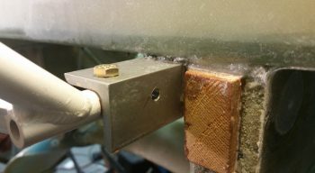
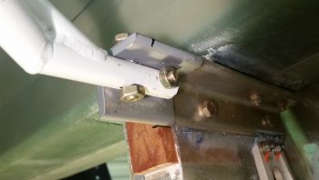
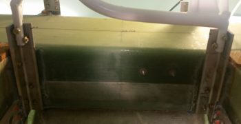
Here we have the finished engine mount bolt holes on the right side:
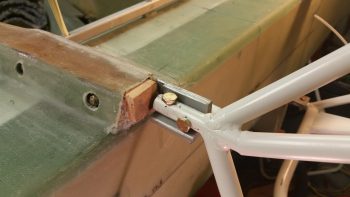
Of course finishing off drilling the lower right engine mount bolt holes meant that both lower engine mount bolt holes were completed.
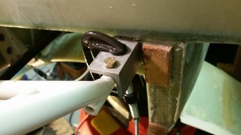
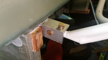
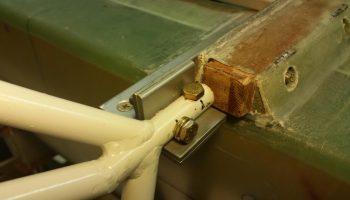
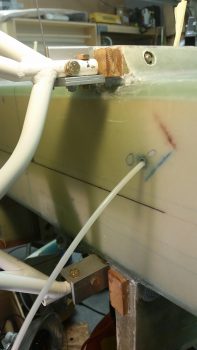
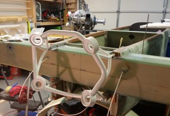
Yes, not a great pic, but the best I have for viewing the fitted temp bolts on the lower engine mounts.
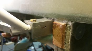
I then finished the engine mount installation by drilling the vertical bolt hole on the upper left engine mount tube. Both this bolt hole and the horizontal took significantly longer with quite a bit more effort than any of the others, because remember in this position the engine mount extrusion is 4130 steel (which may help explain why it’s so much narrower than the other engine mount extrusions).
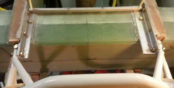
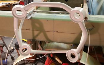
Here’s a shot of the top engine mounts with the bolt holes all drilled.
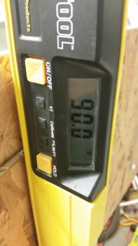
I then double-checked my slightly modified angle and, again, using a 0.224″ spacer (drill bit) vs the plans 1/4″ (0.25″) spacer, I was at exactly 90° [Note that although the board is in place on the engine mount, I am measuring the angle with my contact points for the level and spacer positioned on the board as if there was no board present].
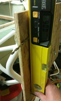
Bam Baby! 90° on the nose . . . now that’s the money shot!
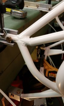
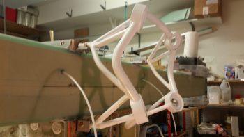
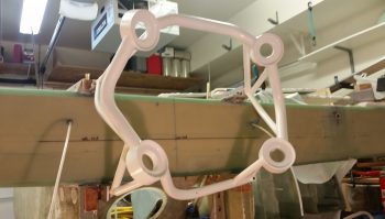
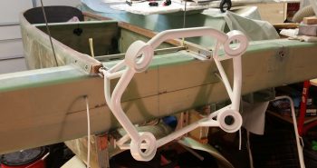
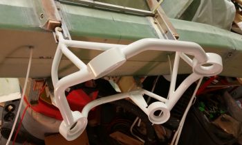
Here I will regale you with a plethora of officially installed engine mount pics!
Tomorrow I’ll be doing a fair amount of work in the Hell Hole in prep for the installation of the firewall that should be taking place within the next 3-4 days.
Bang on job, Bro!
Thanks Brother!