
Initial engine mount install that is…
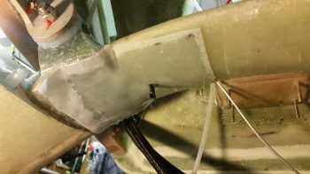
I started off today by trimming down and then rough sanding the foam plugs that I have micro’d in place over each outboard end of the lower extrusions’ bolts, nuts, and wide area washers…. for both the right and left sides.
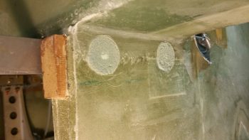
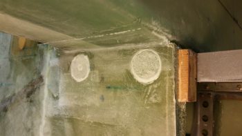
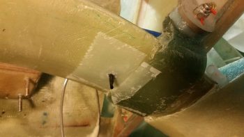
I then removed the engine mount –which is a tight fit– exposing the 4 engine mounting extrusions.
here’s a closer look . . .
Using the taped up SD-8 relay and some 5-min glue, I mounted the 2 SD-8 relay Clickbonds on the underside of the CS Spar towards the right side a bit.
When I was making up my 3×5 card task list this morning, I also decided to verify my desired locations for the right and left brake line runs. I wanted them below the main gear so they were as accessible as possible via the bottom Hell Hell cover (disguising itself as an intake scoop) once the plane is completed.
I confirmed the positions and sanded down the areas that would get a few plies of BID to secure the Clickbonds into place. BTW, the Adels that are getting mounted to these Clickbonds won’t directly clamp to the brake lines, but rather will secure each side’s 3/16″ (from the wheel calipers) to 1/8″ (fuselage brake line run) Generant reducer fitting.
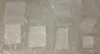
As the 5-min glue set, I then prepregged all the BID for laying up over the Clickbonds. Just before mixing up some epoxy with fast hardener, I wrapped each Clickbond threaded post with a small piece of electrical tape to protect against any epoxy gunk.
I then laid up 3 plies of BID over the SD-8 Relay’s Clickbonds and then peel plied it.
And did the same for the right & left side brake line Clickbonds.
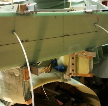
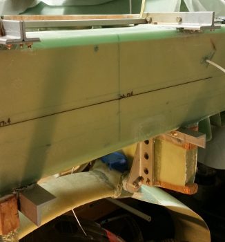
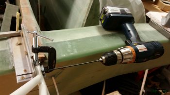
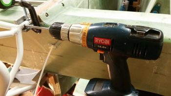
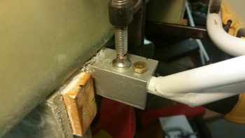
I then got to work on drilling the engine mount bolt holes. I had an entire plan of drilling the engine mount with it off the extrusions, since I was thinking there wouldn’t be enough clearance for a drill to get a straight shot at drilling the bolt holes. There may not be enough clearance for the bottom horizontal bolt holes, which are forward on the bottom, but for the top horizontal bolts (which are the aft positioned holes) there’s plenty of room.
Also, instead of messing around with some inherent induced error by measuring from F28 or the panel, I went straight to the tip of the extended pitot tube to measure the final position for the top engine mount cups to get them both at F.S. 134.2 AND equidistant from the very front tip of the plane [to be clear, I did FIRST confirm F.S. 134.2 from F28 since I needed a known F.S. to measure off of]. I’m fairly certain I’m off maybe 1/32″ at the most… maybe, maybe just a hair higher if we account for any flex and angle of the measuring tape, but definitely close enough that “these dogs will hunt!”
After drilling a very small pilot hole just enough to guide a larger bit, I switched to a long 1/8″ drill bit for the initial round, then stepped up a couple bit sizes each round. Of course, going through 4130 took a bit for the initial hole, but went smoothly after that.
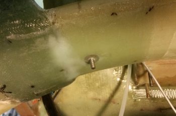
Here’s the break through on the right side.
And the left.
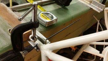
I then used a 0.25″ reamer, that actually measures out at about 0.246″ on the calipers. Perfect, I thought, but there was no resistance to the bolts when I slid them into the bolt holes. Disappointing, but follows in line with what my buddy Dave Berenholtz experienced when he drilled his engine mount holes down in OZ (And here I just thought it was a hemispherical gravitational thing on his part . . . ha!)
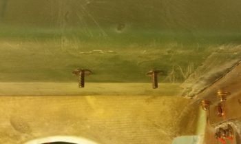
Here’s the nicely aligned but not-as-tight-as-it-could-be bolt test fit in the upper right engine mount horizontal bolt hole.

And let’s not forget the left side. Same story.
I don’t have any pics of my next task, but with my top horizontal bolt holes drilled, and thus the top side of the engine mount configuration locked in, I spent a good half hour aligning the bottom engine mount tabs (using a squeeze-handle style clamp) so that the engine mount aligns leaning forward 2° at the top, which is the plans position. Again, however, the plans was set up with a 118-125 HP O-235 motor in mind, while I’ll be pushing 180-190 HP.
However, after rereading Dave B’s account on setting his engine mount, I realized that I had misread what my fellow Long-EZ builder had ascertained about the translation of the 2° figure. So, in the end, knowing that I wanted the aft side of my engine just a hair lower than that of an O-235 Long-EZ, I replaced the typical 1/4″ spacer at the top the engine mount when measuring for this 2° angle (derived during the build by setting the plans F.S. for the bottom mount at 134.45) with a drill bit 0.224″ in diameter. This engine mount angle and alignment is of course checked by getting 90° on the level with the bottom against the engine mount and the spacer wedged in between the level and engine mount at top.
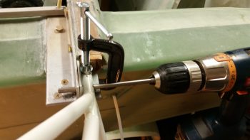
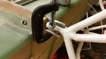
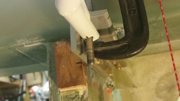
Once I dialed in my engine mount angle, I clamped the engine mount tubes to the lower engine mount extrusions.
I then started drilling the bottom left engine mount vertical bolt hole, which again, the aft bolt holes on the lower mounts are vertical. I marked my hole from below, and again drilled just enough of a small starter hole to align the bit. However, that experience alone told me there was no way I was going to drill a hole UP through 4130 for as long I would need to break through this thick steel tube.
So I carefully measured out the tube centerline and extrapolated all that data up to the top of the engine mount extrusion, and drilled from the top down. Ahh, much easier!
I did use the reamer, not surprisingly with the same underwhelming results as I got on the top side bolt holes.
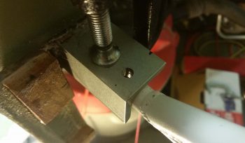
However, I decided to add a new twist (this is a pun . . . you’ll see!) to the lower left mount tube’s vertical bolt hole by getting the bolt hole just slightly off center. The “twist” reference above is because the actual engine mount extrusion is slanted just a hair inboard at the top.
Thus, when I drilled straight down I was in fact relationally at an angle on the lower engine mount tube. Not far enough off center to cause structural concern, especially with this super strong and rather forgiving 4130 steel, I just lose some major style and good craftsmanship points for this “infraction.”

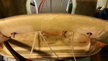
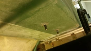
I then grabbed a quick dinner with an old military buddy of mine and when I returned I pulled the peel ply off all my cured Clickbond install layups… which all turned out pretty good. Here’s the SD-8 relay mounting Clickbonds on the underside of the CS Spar. BTW, I positioned these forward enough to be out of the way and not induce any added hassle when I layup the corner BID tape between the forward side of the firewall and the CS Spar
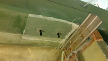
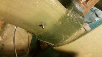
Here are the cured BID layups for the lower right (upper pic) and left brake line securing Clickbonds.
Tomorrow I’ll continue with my engine mount installation, although I will need to assess my reamer issue. I think I’ll try drilling out the lower right extrusion’s vertical bolt hole with just a 1/4″ bit and see what kind of result I get (obviously builders have been doing this for years with no reported adverse affects).