
Well, after about 6 years I finally finished Chapter 14! Woo-hoo!
I started off by drilling the aft vertical bolt hole on the lower left engine mount extrusion up into the Spruce hardpoint that is imbedded in the CS Spar at all the extrusion attach locations. I double checked my marking that I had made a couple of days ago and then took the plunge!
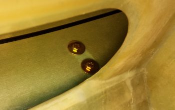
As you can see, it popped through inside the CS Spar at the tail end and center mass in the Spruce hardpoint.
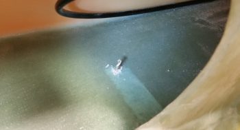
And I got the same result on the right side as well . . . I was definitely starting off the final step of Chapter 14 right with the first bolt hole attempts. Since these 2 bolts are situated so close to the CS Spar’s critical lower spar cap, I knew after I avoided hitting it that the bolt installs would only get easier from there.

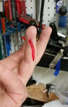
Then, out of nowhere, as I working in the Hell Hole, minding my own business . . . Bam! An early casualty . . . ahhh, precautionary tale: THIS IS WHY I PEEL PLY!!
[Obviously this was in an area I couldn’t reach to peel ply!]
After getting the vertical bolts installed, and just as I finished drilling the aft side hole in the lower right engine mount extrusion, it hit me that I was forgetting something! Ahh, Terry Schubert would be sooooo ashamed if I forgot to seal the wood inside the holes!
So I pulled out the front vertical bolt on each side and left these aft side holes (I had already drilled the outside access for the wide area AN970-4 washers… below) open. I then mixed a small batch of epoxy with fast hardener, added a bit of alcohol to it to thin it out, and then used Q-Tips to get the epoxy slathered onto the bare Spruce inside each hole. I also treated the holes in my longerons for my rollover assembly. I then went upstairs and cooked a fairly quick dinner, took a break, sat down and had a bit to eat.
When I got back the alcohol-epoxy solution was just starting to gel slightly. So I installed the 2 pairs of bolts into the open holes, pulled the aft vertical bolts and hit those holes with the sealing epoxy solution. I then drilled the front side bolt holes on each side. It took a while for me to drill out the front holes, so a bit after I was done I hit the forward pair of the side holes with the alcohol-epoxy solution and then replaced the aft vertical bolts. Wood holes sealed!
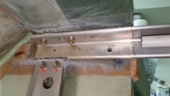
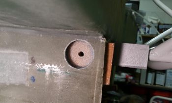
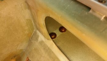
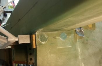
Backtracking a tad, here I’m drilling just the outer sidewall skin and a bit of the foam in order to remove the plug . . .
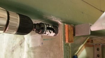
that would allow me to create a nice inset to employ an AN970-4 wide area washer in an area –the exact area as the gear mounts in fact– that is just fiberglass over Spruce. Knowing the issues I had with the narrow washers and bolts digging into the glass & wood, deforming both, in my original main gear mounting, I definitely want to avoid that where my engine mount is concerned. Thus, just as I did on top extrusions, I’ll again be using AN970-4 wide area washers.
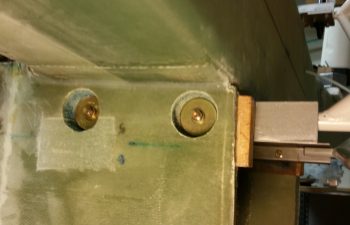
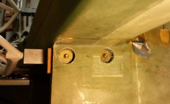
I then mounted both sets of side bolts for the left and right lower engine mount extrusions. I will note that the forward bolt overlaps about a third-to-half of the way into the area that I dug out to install the wide area washers for the top main gear bolts, as is easily seen in the pics below. Again, since the underlying glass and wood was deformed a fair bit on the main gear outboard bolts, I used a bit of flox and BID to add some structural integrity and solid underlayment for the gear wide area washers (again, this was for the main gear bolts).
I said all that to merely state that, unlike the aft extrusion bolt, each of the forward bolt’s washer has a lopsided “floor” or “wall” to rest upon since theres a build up of glass and flox on the bottom side of each hole. To remedy this, I simply added a bunch of thick flox behind each of the 2 forward extrusion bolt washers.
While the flox was curing (I used fast hardener of course) in the forward side pair of extrusion bolts, I took the opportunity to snap some pics of the completed install of the lower engine mount extrusions . . . thus completing Chapter 14!
Here’s shots of the interior bolts (4 each) of each side of the lower engine mount extrusions.
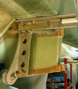
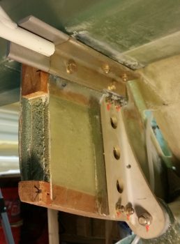
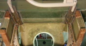
And a shot of the whole shebang!
It’s rather interesting how actual little info there is on this step in the plans. Knowing I didn’t want a huge gash on my arm as I stuffed goodies into the stowage access hole of the CS Spar before a flight, I decided to mount the vertical bolts with the heads inside the CS Spar and the threaded arm-mangling part of each bolt on the bottom (Hell Hole) side.
I should say that I’m really happy with hitting the CS Spar’s embedded hard points. I did very slightly cheat on the front bolts and moved them aft around 0.070″ to 0.1″ to ensure they were on the flat part of the spar (both top and bottom on the front of the CS Spar has an angled corner). This also helped ensure that I could fit a AN970-4 wide area washer in these locations as well.
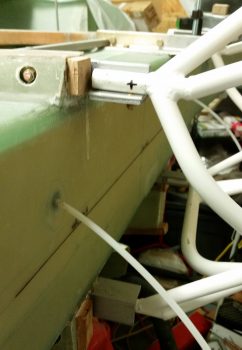
After the flox –serving as the AN970-4 leveling base in the front side holes– was very close to being cured, I snugged down all the side bolts just a pinch and then micro’d in foam plugs I had just made specifically for this purpose.
I’ll let these dry overnight, then sand them flush with the sidewall. However, I probably won’t glass them until I build the strakes and add a bit of glass and Kevlar to the sidewall area near the main tank fuel flow feeds that are embedded in the fuselage sidewalls.
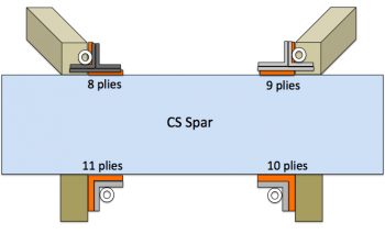
Here’s the tally on how many plies I used on each engine mount extrusion BID pad. As you can see, I met the 7-ply minimum criteria spelled out in the plans.
Tomorrow my main goal is to get the engine mount drilled and mounted onto the engine mount extrusions. After I finish that task I will then install the engine mount onto the engine and then start planning on exactly how to attach that whole monstrosity to the engine stand.
Well done. You nailed all that pretty quickly! Looked painless, except for the blood 😉
Thanks. Yeah, that barb was a stinger!
I guess plan your work and work your plan actually works out at times! ;)