
I started out the day by updating my wheel pants (or “spats”) task list before heading down to the shop. My plan was to get to the point I could knock out a few layups on the wheel pants then roll into finalizing the shop reorganization… with the wings inside and the fuselage having done an about face. But that didn’t happen.
What did happen was a whole lot of mini-tasks getting completed on the wheel pants, which of course has moved the completion bar to I’d say the mid-90% area (excluding finishing of course).
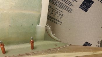
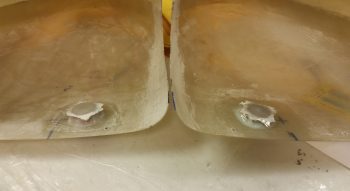
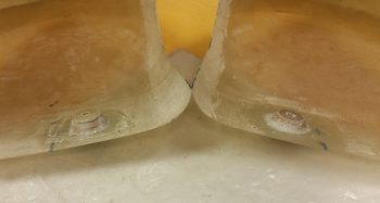
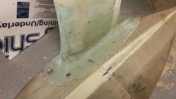
My first task of the day was to trim down the Gear leg to wheel pant bonnet fairing on the aft side of the bonnet. I just couldn’t pass up the opportunity to make a swoosh-style fairing here because when I see canard aircraft with wheel pants without this swoosh fairing . . . well, something is just missing mentally for me. So in they went.
Obviously here is the before-trimmed shot.
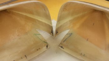
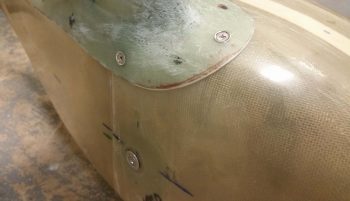
And then after I trimmed down the jagged swoosh fairing edge.
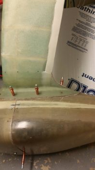
Here we have the right side swoosh fairing after I trimmed it down. I would like to point out that these are initial trimmings, and I’ll dial them in most likely when I finish the wheel pants to paint.

I then set my sights on drilling out the left side bonnet’s front 3 mounting holes for #10 screws. After drilling the front hole I set a #10 screw in place with a narrow Tinnermam-style washer.
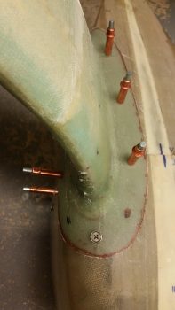
I then did the same after drilling the outboard mounting hole.
With the front side screw holes drilled out (remember, the aft end gets CAMLOCs) on both the left and right wheel pants and bonnets, I then pulled the wheel pants off. I then sanded down the interior edge of the tire openings for the upcoming 2-ply reinforcement BID those will get.
I then laid up 2 plies of BID on “top” (the inboard sides) of the outboard support doublers. Again, this was due to delams caused by the extreme angles from the sides of the doublers to the “top” surface, and something I had a good notion might happen. No worries, small EZ layups and a little flox and they’ll be right as rain.
[Although I forgot to take any pics, I also laid up a ply of BID over each line of flocro that I used to hold the stainless steel brake lines into the gear fairing after bending them out to flare and terminate the ends. The bonnet layups covered the bottom 2/3rds of the channels, but the tops were just bare flocro on the inboard side of the gear legs].
Since my plane has the wide main gear fairing and thus a longer bonnet, I then added a ply of BID on the insides of both aft wheel pants where the CAMLOCs will get mounted. The area where I added the BID is much lighter glassed than the more robust areas of the wheel pants.
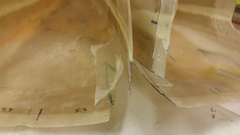
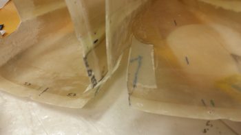
As the glass cured I then got to work sanding and shaping the edges of the wheel pant bonnets that are now permanent fixtures on the gear legs. In addition, I spent about 10-15 minutes per side digging out the transition-fillet-creating Play-doh from under the bonnet.
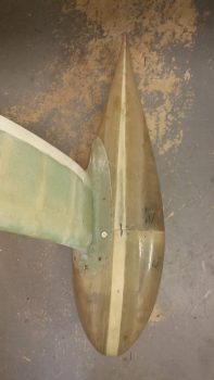
Here’s the right side bonnet cleaned up and sanded.

A few hours later here are the cured and trimmed support doublers.
And here’s a shot of the K1000-3 nutplates I riveted into place as the glass layups were drying.
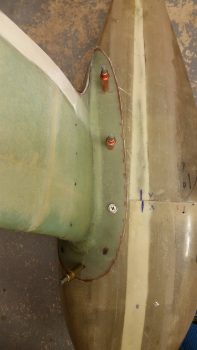
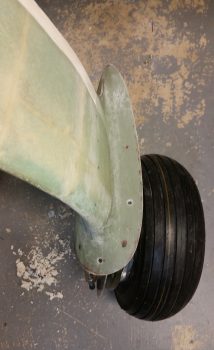
After all the layups had cured and I pulled peel ply and cleaned them all up, I then mocked up the left wheel pant using only screws… no Clecos.
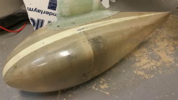
Here you can see the top front 3 screws in place. In actuality I need to get some more screws since only the outboard centerline screw is the right size #10 screw, and doing the lion’s share of the work. The front and inboard are #8 screws that I used to show visually how it all would look. BTW, if you’re wondering why I ended up going with #10 screws, it was simply a matter of visual balance with the CAMLOCs, whose studs have the same size head as the #10 screws. With 5 screws total for each wheel pant, the weight increase is minuscule going with #10 screws vs #8’s.
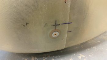
I did what I could to countersink the 1/4-28 side mounting screws, but I will need to pick up an actual 1/4″ 100° countersink from ACS to finish the job. Although the Tinnerman washer sits just a hair proud, this shot of the outboard mounting screw still gives you an idea of how it looks.
Here’s a shot of the screws from the inboard side.
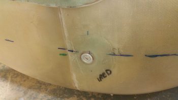
And here’s a shot of the inboard 1/4-28 mounting screw with Tinnerman washer.
Tomorrow I’ll check and make any required adjustments for tire clearances. After/if any cutting is required, I’ll then layup the 2-ply reinforcement layups around the perimeter of the tire openings. After that, the wheel pants will be completed except for the additional mounting hardware that needs to installed (screws, CAMLOCs, etc.) and finishing of them to paint.