
As I mentioned in my project update, I decided that I needed to flip the fuselage right side up to glass the top sides of the gear fairing. I hadn’t planned on flipping the fuselage for quite a while, but plans change when one (read: ME) fails to account for issues such as the heat shields blocking access to the lower outboard gear leg thus preventing glassing the topside gear fairing if the wheels are mounted. Sequencing is key in my opinion for optimizing the build schedule, but in this case there was no way around it: the fuselage was going to have to get flipped back upright.
No big deal of course. I did re-wicker my build steps though to account for the fuselage being right side up. The plan now is to glass the top of the gear fairings, then do a final check & possible tweak of the toe-in, and then mount the wheels/tires/axles/brakes/heat shield. With the wheels in place, and the fuselage upright, I can then mount the wheel pants and be finished with all things gear related except for finalizing the brake line install. As for the stainless steel brake line install, the new timeline works out fine since my stainless steel capable flaring tool won’t be here for another couple weeks.
So I started off today by trimming the TE of both the right & left gear fairings.
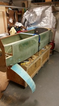
Once I got the gear fairing TE squared away, I needed to flip the fuselage. I did about 10 minutes of head scratching before I finally remembered that I had designed the fuselage dolly so that it could match up height-wise with my portable fold out table. I set the table as you can see below and it matched up great after I set a couple 2x4s with cardboard protectors in place to get the heights equal & matched.
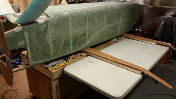
I then very carefully & slowly tipped over the fuselage onto the foldout table using the gear legs as a lever.
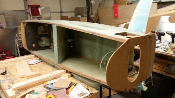
Here’s a shot from the inside cockpit side… something I haven’t seen in while.
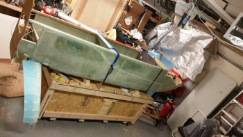
I then slid the fuselage sideways back onto the fuselage dolly.
And then flipped the fuselage right side up back onto the fold out table, and then once again slide it over onto the fuselage dolly. Once I had it blocked correctly underneath, I then reattached the securing straps.
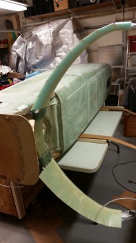
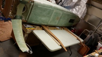
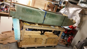
Another shot of the flipped fuselage from the aft end.
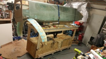
Clearly the bottom side of the gear is close to the ground, someplace that I don’t want to spend a lot of time messing around trying to layup glass. Luckily my fuselage dolly elevates!
Interestingly, with the amount of weight that my fuselage is packing on, my drill couldn’t handle the torque of getting the dolly platform to raise. Actually, I should say that my hand couldn’t handle the torque of the drill wanting to rip out of my hand. So I grabbed a ratchet speed handle and raised the platform its first few inches manually before switching to the drill. [I guess this demonstrates the torque required on the nose gear that Jack discusses in his instructions: to have the gear up at least a foot before climbing in & having it raise passengers from the flat deck position.]
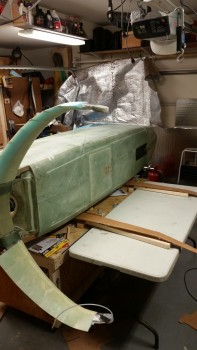
As you can see, I raised the platform its full height giving me (and thus my back!) a much better working height for glassing the top side of the gear fairings.
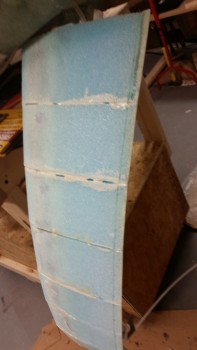
 With the gear height at an acceptable working height, I then marked the right gear fairing a half inch (0.5″) forward of the TE. This will allow for a good top fairing glass to lower fairing glass bond.
I used a razor knife to remove the foam, and then the Dremel Tool to remove the micro that had oozed out the aft end of the foam piece junctions. I also cleaned the dead foam & micro off the freshly exposed TE lip.
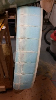
Then came the not so fun step. For some weird reason the “2-piece clamping method” that I used on the right side fairing didn’t work so well. I could run my hand up & down the outer surface of the right fairing and depress the foam inwards towards the original gear. Clearly there were a fair number of air gaps between the applied micro layer and the foam fairing pieces on the right side fairing.
With the size of the air pockets the practical solution was far beyond injecting epoxy or anything else under the foam pieces, I was going to have do a sort of rebuild on this fairing.
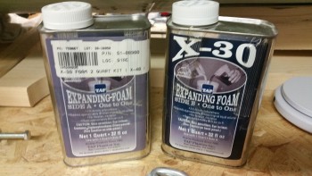
Enter X-30 Expanding Foam. I know a lot of builders have used this foam for a variety of things, but I personally haven’t used it before.
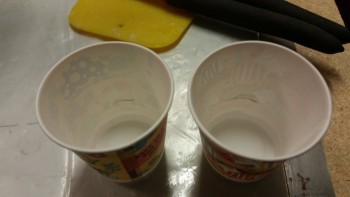
After reading the directions I decided that I would heed the warning of so many builders before me that this stuff really does expand 30 times its initial volume. With this in mind I marked equal pencil lines in 2 small cups less than an inch up for parts A & B of the X-30 foam.
I poured the part A & the part B X-30 foam in the separate small cups, and then as per instructions mixed them in the larger cup.
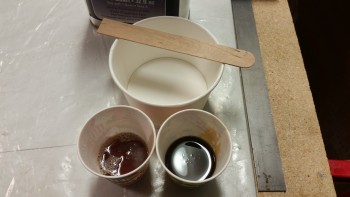
For those not familiar with the X-30 Expanding Foam, it has a 15-20 second mix time before its immediately poured and/or applied to the surface. I didn’t set up any dams or anything since I applied it straight to the surface of the right gear fairing.
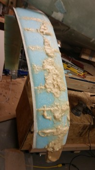
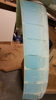
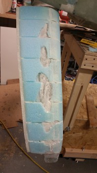
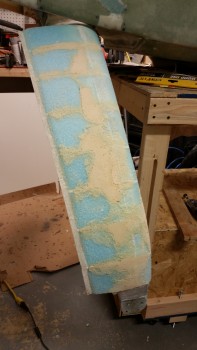
Here’s a wide angle shot of the right gear faring with the expanding pour foam applied to it.
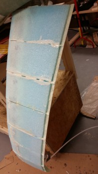
While I let the expanding foam cure some I went to work on the TE of the left gear fairing. As with the right gear fairing I trimmed the foam 0.5″ from the TE.
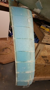
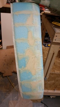
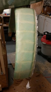
After finishing trimming the TE on the left side, I turned my sights back onto the right side gear fairing. I started out using the Stanley Surfoam grater to trim the foam down (left pic) and then used my sanding board to finalize the foam sanding (right pic).
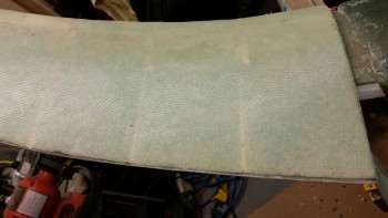
I then cut another 4 pieces of UNI off the roll. This time around I added a half inch to make the width 11-1/2″ wide vs the underside 11″ wide. I cut the UNI at a 30° angle across the entire roll.
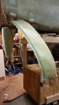
I then mixed up some flox and applied it to the left top gear fairing foam & glass junctions at both the LE & TE. I then micro’d the surface of foam gear fairing before laying up 2 plies of UNI oriented in opposite 30° angles. I overlapped the 2 plies of UNI onto the bottom fairing glass by about 1.5″ the entire length of the LE.
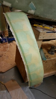
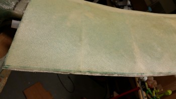
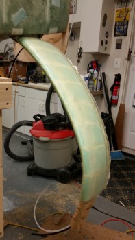
A front shot of the glassed topside left gear fairing.
With the right gear fairing glassed I then sanded down the blue foam & cleaned up the micro on the left fairing with the Dremel tool. Once the fairing surface was prepped, I micro’d the top left gear fairing.

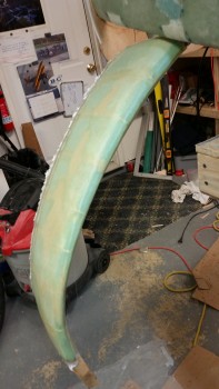
I then laid up 2 plies of UNI at opposite 30° bias just as I did on the right side gear fairing.
After laying up the UNI on the fairing I ensured that it was trimmed on both sides. I also peel plied the UNI overlap onto the lower fairing glass on each side.
Since I used MGS 335 with slow hardener, I have a few hours before I’ll razor cut the overhanging glass. When the layup gets to that green point I’ll also apply dry micro to the depression along the TE.
Once I get the gear fairing cleaned up I’ll confirm the toe-in as I mentioned above.