
3-DAY BLITZ: Day 2
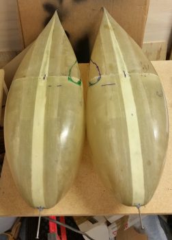
By “no smiles allowed” I am of course referring to the “smiles” that wheel pants that are too narrow often end up with…. a common occurrence in the canard world since wheel pants made primarily for RVs end up looking a bit different on our birds with gear bows.
The cure for this, at least according to Wayne Hicks (and after today, I’m a TRUE believer) is to simply widen the wheel pants… which I did. Of course we discussed this, it’s just been quite some time since I’ve done or posted anything on wheel pants.
I started off today doing the thing that for some reason I dreaded the most for the wheel pants installation process: making the cardboard cutout templates of the wheel & gear. Of course, just about like anything else once you actually get going on it then it’s not that bad… such was the case here.
I started at the front of the wheel and moved aft, incrementally removing any piece of poster board that prevented me from moving it aft. Here a shot of round 2 or 3 of poster board removal.
After about half an hour of slowing cutting and hacking away parts of the poster board, I was finally finished with my first poster board gear cutout template.
Here’s a shot from the front . . . and as you can see, my template wouldn’t win any contests!
Of course the one from the side was infinitely more easy and I had it knocked out in 10 min at the most.
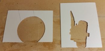
These cutout templates are used to determine the front/aft edges of the tire hole, the right/left edges of the tire hole and the location of the cutout for the gear strut. They pretty much give you everything you need for the tire cutout, but for the gear strut cutout, what it doesn’t provide is the angle.
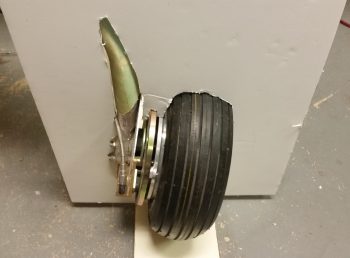
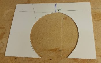
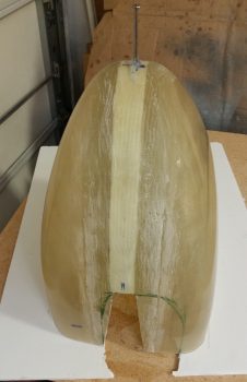
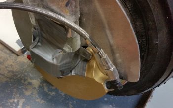
I started with with the side silhouette cutout and marked both the vertical axle line (in blue) and the 3/8″ minimum clearance gap (in green) between the top of the tire and the underside/inside top of the gear pant [which is why we ensure the tires are at max PSI].
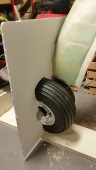
I started with the right wheel pant and marked the front/aft tire cutout lines and the location and width of the gear strut.
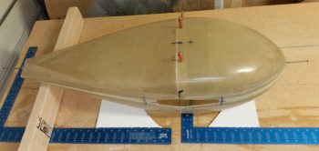
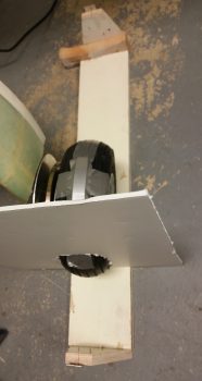
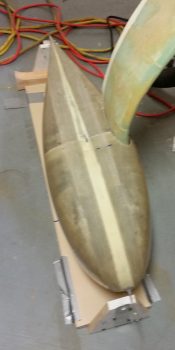
Here’s a more direct down view, showing that the top of the wheel pant is aligned with the 3/8″ line to ensure inside top clearance with the tire. Once this is done, it automatically dictates how much of the tire will show through on the bottom. To get the wheel pant aligned properly nose/tail up or down (waterline), I made pencil hash marks at 6″ in the front and aft sides on the table, and aligned the nails with those marks.
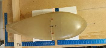
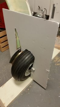
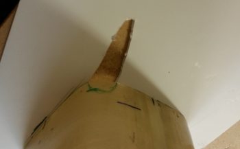
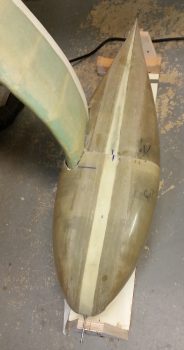
I then broke the wheel pants into its 2 pieces and used the front piece to determine left/right edges of the tire cutout (the one shown below is the left side wheel pant). As you can see, with our gear struts and wheel assemblies taking up so much room inside the wheel pants, it really pushes the tire wheel pant exit far outboard.
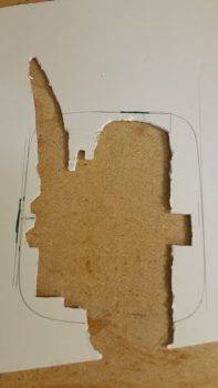
Before making the final tire exit marks on the wheel pant, I verified clearances and dimensions by drawing the outline of the wheel pant onto the cutout template. This really does help figure out all the wheel pant mounting, since in my case I had planned on using a 1/4″ wood spacer on the inboard side of the wheel pant as called out for in the installation instructions. However, even though I widened my wheel pants I still felt the outboard wheel pant side was too close to the wheel/tire. Thus, I changed the plan and went with a 1/8″ inboard spacer to drive the entire wheel pant outboard 1/8″. Not a lot, but every bit helps in ensuring NO SMILES on the side of the wheel pant!
I then marked the location for the gear strut width-wise.
Here are the initial markings for the tire cutouts on the bottom of the wheel pants. If you want to know what side is what, just imagine the plane flying upside down.
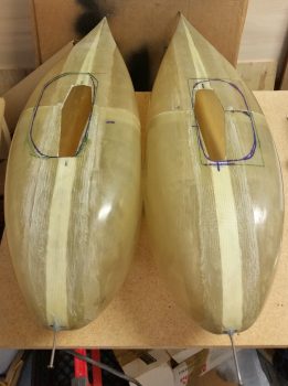
And here are the initial markings for the landing gear strut holes.
Since my inboard wheel pant mount is 1/2″ thick, and the new thickness for my inboard wheel pant spacer is 1/8″, I added a hair for flox and glass and made a foam spacer for each inboard side (R/L) at 0.65″ thick and taped them in place.
After determining and setting wheel pant jigs to match the CL of the aircraft, I then spent the next 4+ hours doing the iterative, trial-and-error: test fit-mark-cut-test fit-mark-cut loop. But I eventually got both wheel pants dialed in and set in place. It is truly amazing how much these wheel pants change the entire character of the airplane when mounted in place.
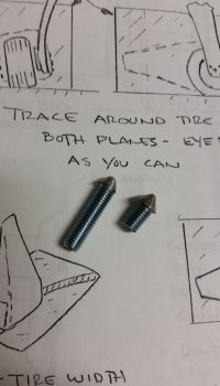
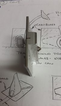
It was getting towards the end of the evening and I had a fair amount of noise to make, so I got to work setting some standard grade 1/4-28 bolts into a drill and then using the drill on the grinder to make some “whack-a-bolts”! These little babies are threaded into the inboard and outboard wheel pant mounts, then when the time is right… BAM! You whack from the outside of the wheel pant and it makes a nice mark and/or indent (depending on how hard you whack it!) so you know right where your mounting screw hole needs to be drilled.
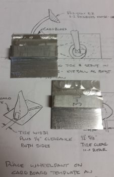
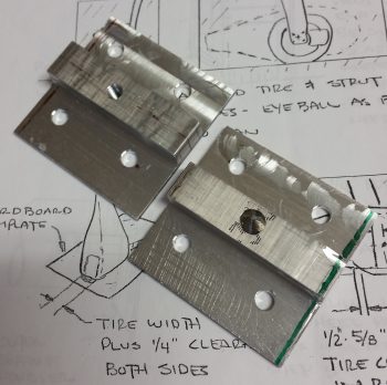
Here are my inboard mounting brackets that I made up a long time ago, using tried and true Neanderthal machining methods! . . . ha! They need some TLC in the surface smoothing department, but I’ll wait until I have them cut to the specific size and shape for each wheel before I make them look all nice.
I then transferred the bolt hole pattern of the 4 right axle bolts and drilled those out on the right-side inboard wheel pant mounting bracket. I then drilled and tapped a 1/4-28 hole in the center for the inboard wheel pant mounting screw.
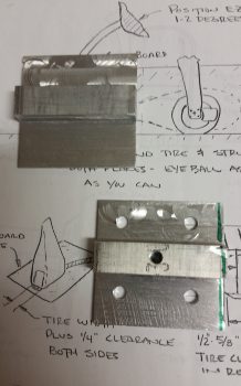
I then threaded in the shorter of the two “whack-a-bolts” into the right wheel pant inboard mounting bracket.
I then transferred the bolt pattern and drilled the four 1/4″ axle bolt mounting holes into the left side wheel pant inboard mounting bracket. I then drilled and tapped the center 1/4-28 inboard mounting screw hole, just as I did on the right side mounting bracket.
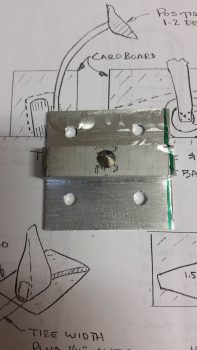
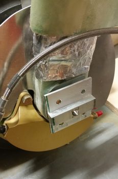
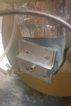
So you get an idea of just what I’m on about with these wheel pant inboard mounting brackets, I mocked them up quickly (just set over top of the axle bolts) to grab some pics of them “in action.”
The one on the right wheel still has the “whack-a-bolt” in it, and the one on the left side has a 1/4-28 mounting screw threaded into it. Again, I’ll do a lot of cutting, shaping and cleaning on these inboard mounting brackets before their final installs.
Tomorrow will be Day 3 of the 3-DAY BLITZ. I’m fairly confident I can get these wheel pants pretty much installed. There may still be a few minor tasks left to do after tomorrow, but the overwhelming lion’s share of the install should definitely be finished!