Well, as with all currencies in the world, including building currency, we must account for inflation . . . so, unfortunately, I see my 3-DAY BLITZ turning into a 4-DAY BLITZ…. ha!
I need those couple hours of cleaning up the firewall that I spent on Day 1 back (wink). And what I didn’t count on today was everything about working the inboard wheel pants mounting brackets taking 3x longer than I had anticipated. I figured 1.5-2 hours to finish the brackets, but it ended up taking well over 3.5 hours to finish them. I am of course super happy that they are done and in the history books.
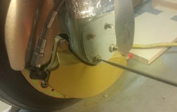
Starting on the right gear leg, the top 2 gear bolts were tight enough that I could get the temp thin-line nuts off the bolts. However, the bottom two just spun freely, so I had to Dremel a slot in the end of each one to enable using a slotted screwdriver to remove each nut.
As an aside, when I chose the lengths of the axle bolts I had in mind a wheel pant bracket of 0.050-0.060″ thick, not about twice that which I have on these brackets. So, the wheel axle bolts will need to be swapped out for longer bolts, but LATER since I’m only concerned about getting the wheel pants on at this point and time.
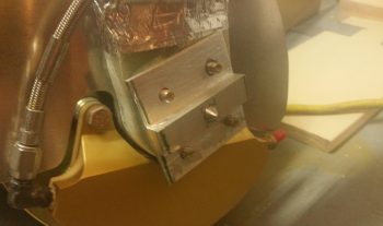
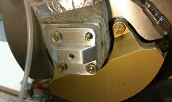
Once I got all the securing hardware off the axle bolts, I was then able to test fit the right inboard wheel pant mounting bracket. I will say that looking at the pic below, for some odd reason the upper right bolt hole came out a good 1/16″ out of position, so I widened the hole into an oval shape to get the bracket to fit into place.
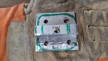
I then marked up the bracket for cutting and shaping. I used my power miter saw, Dremel, hand files and sandpaper to get the bracket that started out looking like this . . .
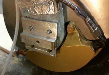
To this state. I think a fair bit easier on the eyes, eh?! I still need a good half hour on each bracket to do a final clean and prep, perhaps even Alodine, which I’ll do when I replace the axle bolts with the final set for the final time.
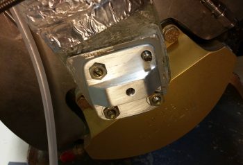
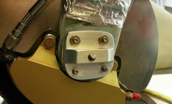 I then started in on the left side. This time it was the upper pair of bolts that required me to Dremel a slot into them in order to remove the temp thin-line nuts I had in place. And I’ll be darned if I didn’t have the top right (as pictured below) bolt hole about 1/16″ off! Not sure what is going on there (maybe I lose interest on bolt hole placement after the third hole and my mind starts wondering . . . haha!)
Here’s the left side inboard wheel pant mounting bracket after I cleaned ‘er up a bit. Again, not bad, but it will need just a bit more to reach its final clean state.
I then spent a good hour dialing in the final position of the right wheel pant. My initial swag of the outboard vertical alignment of the mounting screw position –which is supposed to be 1.5″ forward of the pant seam (get it?! … ) — was off a bit and I needed to remove about another 0.5″ of material in the U-shaped gear leg cutout on the forward half wheel pant. This enabled to move the entire wheel pant aft, as I noted after having to move my jig assembly aft a couple times when the tail of the wheel paint was being physically restrained from free movement by the aft jig upright.
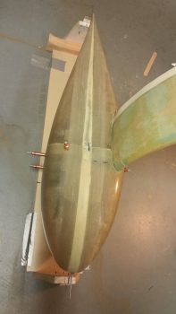
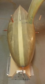
Well, removing material from the top gear strut area alone wasn’t the only requirement of course for getting the entire pant moved aft, since there’s quite a large protrusion called a TIRE at the bottom that had its say as well. So this whole machination of course called for some tire hole lengthening and just a hair of widening to allow the front pant half to move aft, keeping the vertical split line perpendicular to the ground. Of course I eventually got it, was able to get the Clecos in AND align the wheel pant in both pitch and yaw.
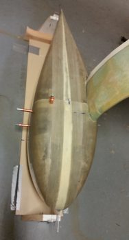
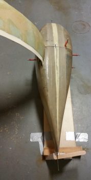
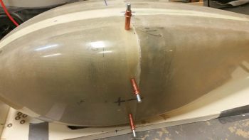
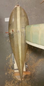
Here’s an aft shot of the right wheel pant in its aligned positioned.
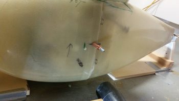
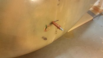
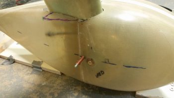
I then got to play “whack-a-bolt” for the first time on the inboard side of the right wheel pant. With the short “whack-a-bolt” pointy thingy installed in the right inboard mounting bracket (which I threaded into place before I aligned the wheel pant above), I then gave it a sharp rap with a rubber mallet. As you can see, it does leave a very nice visible mark to let your know where to drill.
With my first inboard mounting screw position known, I then needed some 1/8″ thick inboard support doublers (I call them spacers, but I want to keep my verbiage understandable….!). BTW, these wheel pants work great with 1/4″ doublers on each side… little did I know what can of worms I was opening by placing all my widths on 1/8″ increments.
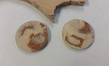
Thus, since I didn’t have any viable 1/8″ material on hand, I then decided I need to make some 1/8″ thick support doublers. I cut out a 1″ circle by using a socket with a diameter just a very scant over 1″, then used my Saber saw to cut out the disk. I cleaned it up with my hard sanding block before using my nifty German saw to cut them right down the middle.
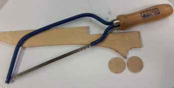 With the resulting interior surfaces looking like this (anyone thinking thick flox . . . cuz’ I am!!)
But the thickness were right in the ballpark I needed, so clearly these little dogs can hunt!
I radiused the edge of the 1″ diameter support doubler disk and sanded the inside edge of the wheel pant A LOT.
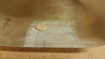
I then floxed the 1″ round ~1/8″ thick support doubler in place and covered it with 2-plies of BID.
I then set my sights on the left wheel pant and worked on it for a good hour or so as the layup on the support doubler cured. I then drilled out the hole in the center of the doubler to 1/4″ and Voila! She works!
I then set the “Whack-a-bolt” in the VANs outboard wheel pant bracket and reassembled the right side wheel pant with the 1/4″ inboard mounting screw in place. I ensured the alignment looked good and left the right wheel pant alone for a bit while I focused on the left side.
Getting the left side wheel pant to its final alignment state took about 20 minutes of course since I knew I had a bunch of material to remove on the front wheel pant half and wasn’t as gingerly in my initial removal of the wheel pant fiberglass.
I then did “Whack-a-bolt” round 2 on the inboard side of the left wheel pant, floxed and glassed the 1/8″ support doubler in place, drilled out the center hole to 1/4″, then tested the 1/4″ mounting screw and doubler placement by reassembling the wheel pant and aligning it (after it cured of course).
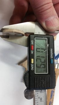
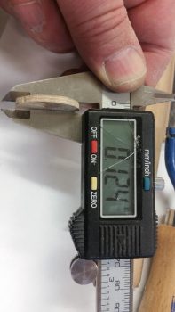
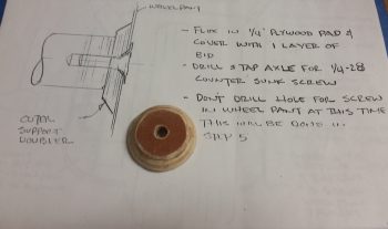
By this point I had already played “Whack-a-bolt” round 3 on the outboard side of the right wheel pant. Here’s the 0.4″ thick support doubler I made up for the right side wheel pant. To get the correct thickness I cut out a 1.3″ diameter disk of 0.375″ (3/8″) thick plywood (dense), removed the top ply of the plywood layers for a resulting thickness of ~0.34″. I then simply 5-min glued a 1″ diameter disk of 0.063″ (1/16″) thick phenolic to the top of it. I then continued the taper of the lower wood disk onto the phenolic to come up with my ~0.4″ thick support doubler.
I then drilled out the 1/4″ mounting hole on the right outboard wheel pant, installed a greased up bolt through the support doubler that I had floxed to the inside of the forward wheel pant. I then reassembled the entire wheel pant, with Clecos holding in place and the inboard 1/4″ mounting screw installed. I then aligned the right side wheel pant as the outboard support doubler flox cured.
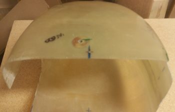
I then repeated the process for the outboard support doubler on the left side, although it required a 0.5″ thick doubler [this makes sense since I could tell while determining and marking the wheel openings that the left wheel pant was slightly larger than the right]. I first played the final round of “Whack-a-bolt” (as shown below), disassembled the wheel pant and drilled out the 1/4″ hole where the point thingy left its mark.
[Some points of note on my wheel pants: I followed a combined set of instructions, primarily based on Gary Hertzler’s original instructions as interpreted by Wayne Hicks… with some smattering of Bernie Siu’s processes here and there. Although I don’t see an issue since the 3/8″ gap on the top is the determinant measurement and I kept the wheel pant sides parallel to the wheel side…. however, on both side wheel pants my outboard mounting bolt hole is 1.2″ lower than the center waterline. This actually appears to be in line with what is shown –but not stated– in Gary Hertzler’s installation instructions. One final point on this is that my outboard mounting bolts are 0.8″ lower than my inboard mounting holes on both wheel pants. Thus, the outboard side is canted up a bit if looking at the wheel pants from the head on view…..technically, since I don’t see anything that looks off.]
Then, just as on the right side, I floxed the outboard doubler in place and used a greased bolt to hold it in place tightly against the VANs outboard wheel pant bracket (taped up to protect against nasties). I then reassembled the wheel pant with Clecos and the inboard 1/4″ mounting screw while assuring it was aligned both in pitch and yaw.
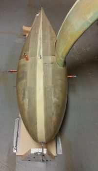
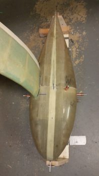
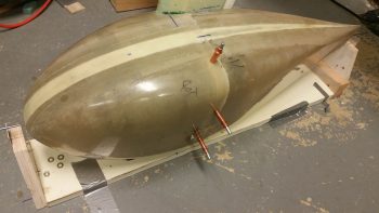
Here’s a final overhead shot of my left wheel pant with the outboard support doubler floxed in place and clamped down with a bolt into the outboard mounting bracket.
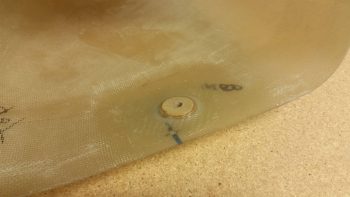
I let the flox cure (I used fast hardener) for about 1.5 hours before I removed the wheel pant and laid up a ply of BID over the outboard support doubler. With all my support doublers then glassed, I called it a night.
Tomorrow I’ll have some fun with Play-doh as I finish the last major step on the wheel pants installation: fabricating the gear leg bonnet. I know I missed finishing my wheel pants within my 3-DAY BLITZ, but hey, if I can knock them out in 4 days, with a few minor outstanding tasks to do… I’ll take that any day!

