
I started off today by test fitting the right heat shield onto the gear leg. The foam of the lower gear fairing extended out enough to make it impossible to mount the heat shield in its correct position.
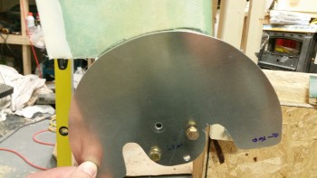
I marked the perimeter of the heat shield onto the lower gear leg in preparation to cut the glass & foam away from the lower gear leg.
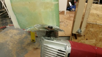
I then used the Fein saw to cut away the glass & foam away from the lower gear leg to allow the heat shield to fit correctly in place.
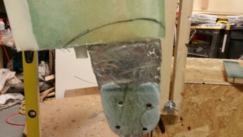
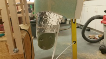
Here’s a shot of the trimmed lower right gear leg.
I then remounted the right gear heat shield, which fit fine. I held the AN4-22A bolts in place with spring clamps.
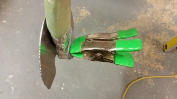
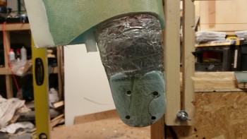
I then repeated this process on the left side to clear the lower gear leg glass & foam (and micro) to allow the left heat shield to fit correctly.
I ran a line down the fuselage CL to double check the toe-in, and even sanded the gear axle mount pads, but after dialing them in as best I could I realized that I was about as close as I was going to get at this point. I’ll do some final checks with the fuselage actually sitting on the ground.
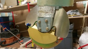
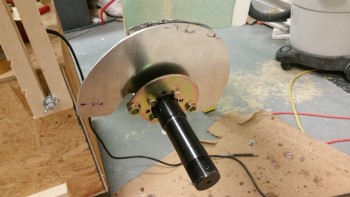
After messing about with the toe-in and dialing it in as best possible, I then mounted the axle, brake mount assembly and the heat shield onto the right gear leg.
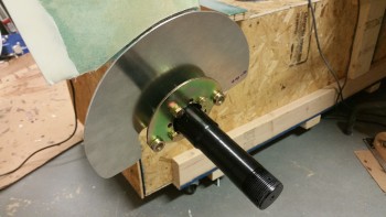
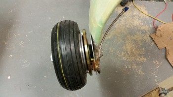
I then mounted the right brake rotor and brake caliper assembly.
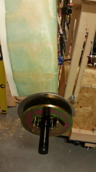
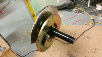
Here’s an inside view of the right brake caliper assembly.
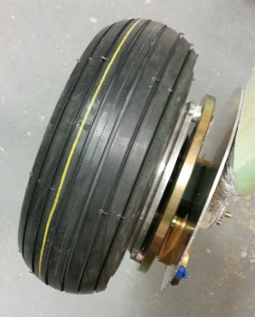
I then installed the wheel & tire onto the right side gear leg.
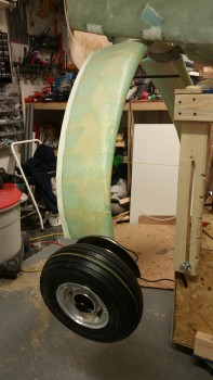
Here’s another shot of the right wheel installed.
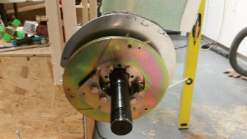
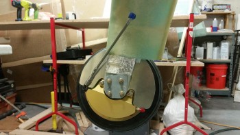
After installed the right wheel, I installed the left axle, heat shield and brake mount assembly. Unfortunately, after tightening up all the nuts on the AN4-22A bolts and then attempting to mount the rotor & brake caliper assembly I realized that I had mounted the brake mount assembly upside down… doh!
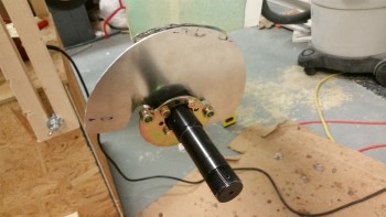
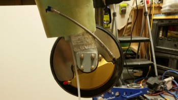
This is how it should look!
I then mounted the left brake rotor & brake caliper assembly.
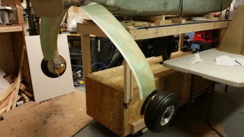
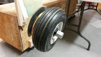
Here is a shot that I’ve been wanting to take for a long time: both wheels mounted!
I then mounted the 9.5″ braided stainless steel Stratoflex brake lines that will connect the brake caliper to the stainless steel brake line tubing.
Here’s an inside view of the right (top) and left (bottom) braided stainless steel Stratoflex brake lines.
I then mounted the wheel axle nut sleeves to both Matco axles. These are sold by Van’s Aircraft for mounting the outboard side of the wheel pants.
With the gear fairings finished and the wheels now mounted, I will start the process of installing the wheel pants. After I get the wheel pants installed, I’ll then flip the fuselage back over, finalize installing the brake lines. Finally, I’ll then work on the RAM air scoop and aft fuselage extension over the hell hole area.