
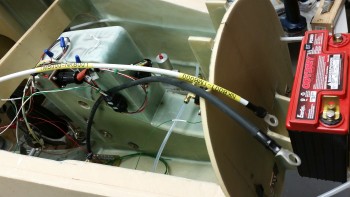
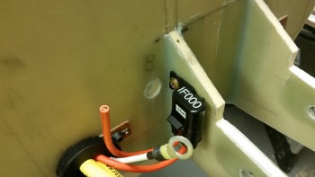
The first 2 pics below are pics I actually took on Christmas. I didn’t do much in the shop, but I did actually get a fair amount of stuff done on the computer, updating spreadsheets, etc. I also printed out some labels for the 6 AWG wire that powers the main buss from the battery contactor, and the 8 AWG wire that links the starter to the starter contactor.
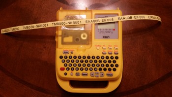
You can see the white 6 AWG cable labeled below. It’s paired/will be paired with the black 4 AWG panel ground cable (I bought it when I had a different configuration, but it will still work fine).
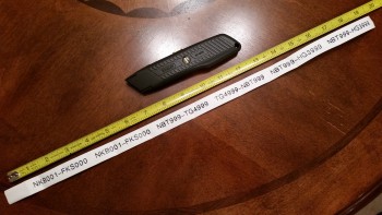
This morning I printed out the 1/2″ big labels for the black panel ground cable above, and also for the big yellow power wires that will run the length of the fuselage.
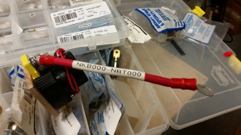
I also printed off one label for the big battery cross-connect cable that provides the power to the battery contactor. (Later on, after mocking all the nose battery compartment components up I just couldn’t make this cable work. Since it’s “technically” supposed to be 6″ long, and it will be more like 11-12″ long, I’m upgrading the cable to a bigger 2/0 AWG cable to allow for the impedance from the extra cable length. I ordered the new cable this evening).
The next task on my to-do list was to add about a 1/4″ to the left side of the F-7.75 bulkhead. I could offer conjecture on what happened, but it was simply a product of the “layup from hell” that occurred when I mounted the BC1s to the front F-7.75 bulkhead. The bottom line was that I jacked it up pretty good, and just like all the sins from the past that I highlight now & then, this is one of them.
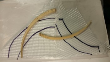
I cut out 2 pieces of H100 high density foam into what you’d essentially see in the last phase of the moon when it’s nothing but a sliver, only in 2 pieces. The widest point, where the 2 pieces meet at the 90° point on the left side, is 0.25″.
I then grabbed 2 pairs of triangular scrap pieces of BID, and put them in plastic for a prepreg setup.
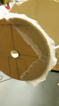
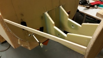
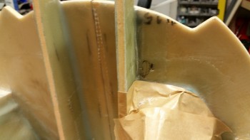
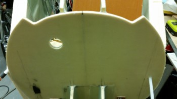
Here’s my “PacMan” layup after I floxed on the 2 pieces of foam, laid up 1-ply of BID over the foam and adjacent F-7.75 glass, and then peel plied it.
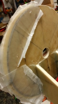
Here’s the aft view.
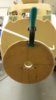
I set up a heat lamp on the layup and headed out to run some errands. It was cured by the time I returned. I pulled the peel ply, razor trimmed & sanded the edges, and then used a scrap piece of wood to check the distances from the bulkheads on each side.
First the left side…
And thankfully it matched the right side! I’m back in business and my distances are the same between the bulkheads on each side, and from the center of F-7.75 in each direction left & right.
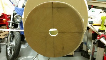
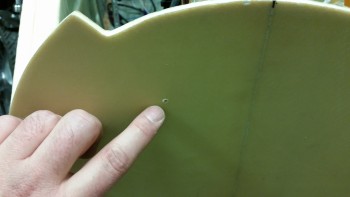
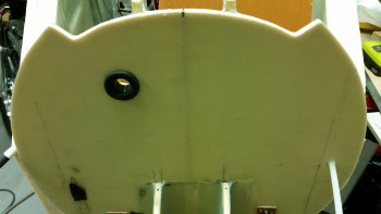
I used a sanding drum on my drill to widen the center pitot tube access hole. There wasn’t a lot of finesse using the drill, but it’s big enough and close enough for what I need now. I’ll dress it up more symmetrical later [believe it or not, all my actions today are in attempt to get to filling in the battery compartment floor & sides with foam!]
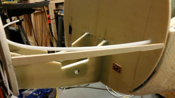
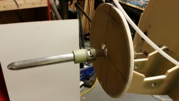
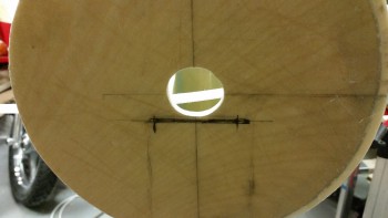
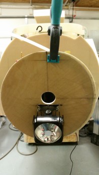
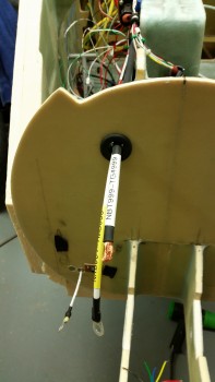
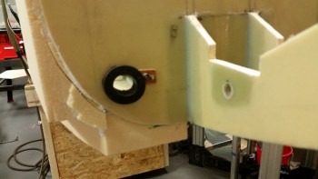
I then mocked up the pitot tube to get the correct spacing & clearance for the landing light. If you haven’t seen my heated pitot tube in action, then you may be wondering about this setup. The light green material at the aft side of the pitot tube is G10. There’s more of this G10 that will cover the pitot tube for a few inches from the forward end of the G10 shown.
Also, if you look at the G10 in the pic, you can see a slot & a notch, which is for use on the ground. When this bird is ready to graze, I’ll simply pull the pitot tube out slightly (forward), turn it about 90° starboard and then push into the nose until it’s almost hidden away. This will keep any crumb-crunchers (okay, anyone!) from stepping on the tube when at fly-ins, etc.
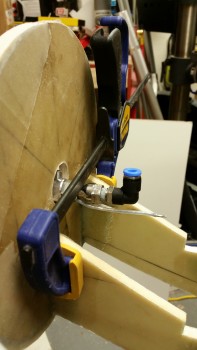
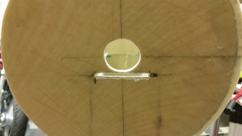
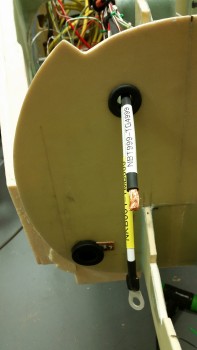
Here’s how I kept it in place on the aft side.
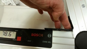
I messed around with the landing light to get an idea of how to mount it. The landing light is an AeroLED MicroSun light that includes the wig wag feature. I bent the mount (that I bought separately) so that it positioned the light at an 11.4° down angle as shown below:
Since I need absolutely all the space I can get for the light to just barely fit into the nose area, I marked the front of the F-7.75 bulkhead to cut a slot for the landing light bracket to actually get mounted on the AFT side of the F-7.75 bulkhead in the battery compartment, so that only the mounting arm will stick out of the front of the nose bulkhead.
Here’s a shot after I finished cutting the slot for the landing light mounting bracket.
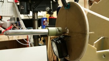
Below is a longer view of the slot cutout, and then a front view of the landing light installed.
This is the crux of what I was after by messing with the landing light & the pitot tube at this juncture: the clearance & space between the pitot tube and landing light, and of course getting a handle on the wire runs for both of these components.
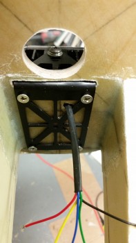
And here’s the aft side of F-7.75 in the batter compartment where the majority of the landing light bracket will reside. This is a horrible pic in that you can see how far off I ended up being on the install of this bulkhead… blech! If you added about a 1/4″ to the left side you can see where it would match up.
One good thing is that by widening it, I’ll get just a touch more of the “F-16” nose look with the nose just slightly wider than it is tall. We’ll see!
BTW, remember me saying that my “Spidey senses” were tingling a couple days ago… making me not want to micro the middle H100 foam piece in between the BC1s? Well, I honestly didn’t think at that point about mounting the landing light bracket where it is now. It would have been a real pain trying to do this with that foam micro’d in place!
I grabbed a couple of alligator clip wire connectors from upstairs along with an inline 3 amp fuse and quickly fired up both the light and the wig wag feature to ensure all was good with my light (and do some mental night landings!)
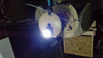
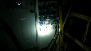
Here’s the beam on the wall about 6-7 feet in front of the nose. As you can see, this beam is very tight, so it will need to be aimed correctly, but will make for a nice landing light. This is just the beginning since I’ll end up having enough lights on this thing to make it look like a UFO!
Here’s a very short video I made showing the landing light’s wig wag feature:
Next, in preparing to cut the foam panels for the battery compartment, I wanted to get all the electrical components placed & configured. To do this, I had to know exactly where my wire/cable runs would terminate.
I started with the B-hole (vs the A-hole . . . haha! Some seriously LOL right now!) On my diagram for the wire runs that I posted a few days ago, I showed that I was going to run everything through 2 holes in Napster: hole A & hole B. Well, that morphed into 3 holes, A, B & C. The hole I started drilling here is the new hole B.
After taping some stuff up to keep it from getting all dusty, I started with a small pilot hole from the aft side of Napster.
And here it is on the front side of Napster.
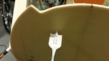
Knowing what my required diameter was, as well as my grommet size, I used a 1-1/8″ spade bit to drill this hole.
Here’s one-eyed evil Napster! [He really started getting so mouthy that I ended up sockin’ him one!] . . .
And here’s black-eyed evil Napster! Ha! [Or maybe the Evil Borg Napster, with that tube sticking out of the side of his cheek!]
I then ran the main buss power cable and panel ground cable through my freshly mounted grommet.
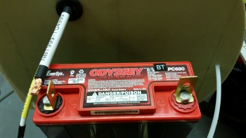
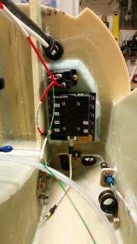
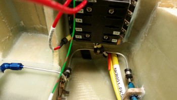
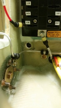
Below is a shot showing the proximity of the panel ground cable to the negative battery terminal. Yes, as with many items on this plane, I bought this cable once I had “finalized” the primary components of my electrical system (Yeah, right!). I found a way to use it though and keep both the power and ground legs to the panel just about as short as you can possibly get in a Long-EZ, barring mounting these on the aft side of F1-3 (Napster).
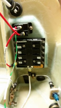
Here’s “the Bridge” that is made up of the main buss power & panel ground cables that will be supported on each side with an Adel clamp. In addition, I’ll be using a high end type of shrink tubing that will really add rigidity and strength to this “cable crossing.”
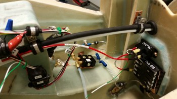
As you can see, the 12 AWG red E-buss power wire coming out of the Battery Buss Relay (mounted on the aft side of Napster on the right in the above pic) will jump aboard with these 2 big cables coming out of the battery compartment. Currently, these 3 cables/wire will be all that is in this run and held in place by these specific Adel clamps (3 total Adel clamps within the NG30 area).
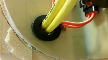
I then started in on the really Big power cables that run the length of the fuselage. I took the two 1/2″ holes that I had drilled previously and cut out the center divider and made them into one big hole. (Yes, this is the “Big A-hole” … haha!).
I spent a good half hour using my Perma-Grit tools and my Dremel Tool to get this thing into a big enough oval so that it would accept the grommet that I bought at an auto parts store tonight. (BTW, I had to modify both of these grommets to get them to fit. I widened the groove on the top grommet for hole B by about 0.060″, and on this one I did a little bit of creative reshaping as well, mainly on the edge that mated with the interior side of the hole).
Here’s a shot of both “grommetted” holes tonight.
I took the pic on the right first, but it’s a tad blurry, so I backed up a bit to get it to focus better. Clearly I decided to post both pics for your viewing pleasure!
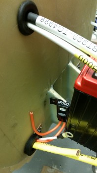
I then ran the big power cables through their Adel clamps & through the hole & grommet to ensure they fit. In addition, I was also looking to ensure that they played well with the other wires that have to traverse Napster via the same hole (I’m talking about the Battery Buss power lead & the SD-8 backup alternator power lead … which is fed by one of the leads coming off the inline fuse in the pic below).
Finally, please note the faint horizontal pencil line in the pic below. This line represents the minimum install height of the battery compartment floor pan. Clearly I’m going to have to dish out a small area to make allowance for the big power cables and the grommet. THIS is exactly why I’m getting this stuff situated, so I can plan out how I need to configure and build the battery compartment bottom & side foam panels.
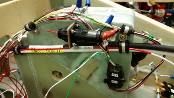
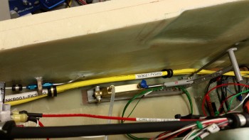
As you can also see, I labeled the top big cable (I’m only using one big cable folded in half for these test fittings, so clearly I’m not going to mark the other side). I thought I’d get a long view shot of the cables in place against the nose side wall.
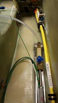
And a close up shot of the big power cables traversing Napster’s domain.
I took this shot more from the perspective of what would be seen when the nose hatch is open.
I played around with the 30 amp inline fuse that sits at the head of the power line for the B&C SD-8 backup alternator (the PM alternator mounted to the engine vacuum pad).
After deciding on a final location, I drilled a hole for mounting it. However, I didn’t actually mount it until I finished drilling the bulkhead hole C, as you can see in the right pic below.
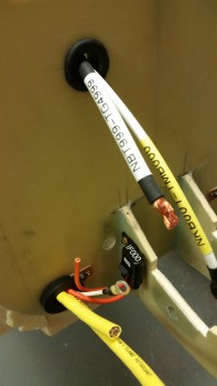
Here’s a closer shot of both the new hole C and the mounted 30A inline fuse. Hole C is where the majority of wires from the battery compartment and nose tip will exit points north and head back to the vast collection of electrons that will reside in, around & near the Triparagon (electrical component “tree” feeding nearly every device in the aircraft).
I drilled hole C exactly 9/16″ in diameter since I do not have a grommet for it on hand, but this hole diameter is exactly what’s required for the grommets I have Teed up & ready to order from McMaster-Carr.
Again, although my endeavors over the past week may have seemed overly electric-centric, I now know exactly how I need to play installing the panels for the battery compartment and the nose for all this stuff to fit nicely. I learned that I’m going to need to position the battery contactor in a slightly different place, and in a slightly different orientation, to greatly facilitate all the power feeds to & from it. To do this after the walls were in place would have made it incredibly more difficult and compounded the amount, time & effort of work greatly.
I can now say that with all this configuring behind me, I really do believe that tomorrow will see the battery compartment panels cut and, at a minimum, micro/floxed in place!