
Today I took a few hours to get some well-needed organization of my hardware knocked out. With all the smaller hardware that I’ve ordered over the last month, I really needed to put it all in some sort of order to make finding stuff occur more quickly and easily.
Due to it being Christmas eve I didn’t get back to the build until later in the evening, and by then I didn’t want to make any noise cutting the foam, so I worked on getting the brake system figured out.
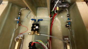
I pulled the right brake line coming in from the aft of the fuselage and cut it shorter, re-flared it, and then connected it back to the mini-bulkhead, I also cut the right brake line that connects to the parking brake valve, and then flared it as well.
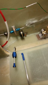
I then connected the parking brake valve to the freshly cut & flared brake line to check fit & alignment.
I then cut, re-flared & remounted the left side brake line that connects to the mini-bulkhead fitting.
I then cut, rerouted slightly and flared the left brake line that leads to the parking brake valve, finalizing the aluminum brake line work in the nose.
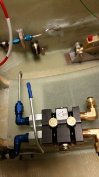
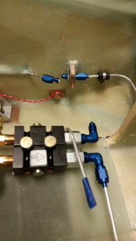
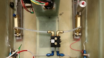
I then connected the other side of the parking brake valve with the nylon brake line included with the Matco parking brake valve
 I had originally planned to mount the clear brake reservoirs on the nose sidewalls, but after messing around with the nylon tubing for a bit, I decided to wait and better figure out the specific configurations and mounting locations for the reservoirs.
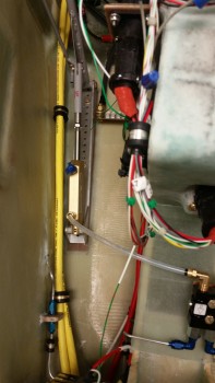
I then test fitted the main power cables in order to finalize the locations of the cable holes transiting from the NG30 side of Napster into the battery compartment. I wanted to get these holes drilled before I installed & laid up the floor plans in the battery compartment.
I then drilled the holes for the main power cables through Napster (not shown), and built the main 6 AWG cable that powers the Main Bus (connecting it to the battery contactor).
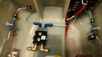
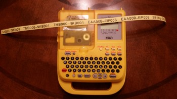
I started by printing out the labels for the 6 AWG main bus power cable, and also the labels for the 8 AWG cable that connects the starter to the starter contactor in the engine compartment.
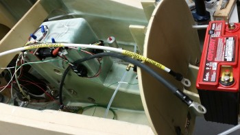
Below is a shot of the 6 AWG main buss power cable that I constructed to finalize the angle and location of the holes to be drilled for this 6 AWG main buss power cable, and the primary ground cable (black cable below) that will be paired up with the power buss cable, both coming from my electric components “tree” –again, I gave it the officious moniker of “Triparagon”– to the battery compartment. This pair of power cables will enter the battery compartment through one of three holes that will be drilled for cable/wire runs. Actually, at least one, and maybe even 2 of these holes will technically be a pair of holes, one for each cable. The holes will be a work in progress so it depends on how the cables & wires actually fit.
Tomorrow is Christmas so I’ll be busy being Merry (ha!), but I do plan on getting an hour or two in on the build (my kids are grown & live on the West Coast so I don’t have any overriding social commitments… sooooo… sniffing some epoxy on Christmas won’t get anyone riled up).