
Yes, it seems to be taking forever to prep & install the ancillary components in order to facilitate item placement in the battery compartment. But I am inching forward.
I started today by pulling the peel ply from the Battery Buss & the E-Buss control relay mounting pad 1-ply BID layup that I did last night. The layup turned out fine without any issues, so I cleaned it up and then drilled out the saran wrap plastic in the 6 embedded nutplates. I’ll tell you, this small stuff is the stuff that turns into time busters, since there’s so many little steps. And at the risk of sounding obnoxiously repetitive, that’s why I want to knock it out during the build –as well as for component planning purposes– so that I don’t end up with a completed airframe with no idea what I’m putting where!
As you can see, I also reinstalled the brake lines. I’m skipping ahead here, but since this info is germane to the brake lines, I’ll tell you that I’m going to have to redo my service loops. After doing an hour or so research on the next steps for the brake system, like the parking brake install & brake reservoirs, I stumbled across some stuff that I either missed or just wasn’t in the Tony Bengalis’ books. Mainly that there should be no sharp bends in the brake lines and to keep it straight as possible. Since I ran across a bunch of ACTUAL loops in steel & aluminum brake lines in my recent research, I figured about half a sine wave would be less stress inducing than a full 360° loop, but I guess any sharper type curvature is bad, so I’ll be remedying that soon.
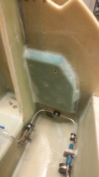
Clearly I’ve been giving my electrical system a fair amount of attention. The main effort here with this mounting pad was to get the battery buss on the aft side of Napster (the F1-3 bulkhead) to minimize the number of wires going through Napster. In addition, it utilizes space that up until this point was unclaimed, but some good real estate. Finally, with the battery buss installed, I get a much clearer picture of where my holes need to go for the multitude of wire heading to the north end of the nose.
To get a minor jump on my electrical system, I went ahead and wired up the foundational wire runs between A) the battery contactor & the battery buss, B) the E-bus controlling relay to the battery buss/switch/E-Bus.
The work on the Battery Bus area included labeling the buss and the wires, crimping on the correct terminals, and confirming wire sizes and wire lengths. Speaking of wire size, I committed a sin against Bob Nuckolls’ teachings since after reviewing my electrical wiring requirements I finally realized that I have a lot of long 14 AWG wire runs. The feed from the Battery Buss to E-Bus is ID’d as a 14 ga wire, but since I had an extra 10 ft or so of 12 ga red wire, I used that instead. That frees up my 14 ga wires for the really long runs where it would be a heck of a lot heavier to sub a higher gauge wire for the length of the fuselage, compared to the 2-3′ that I just did.
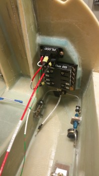
Below is the Battery Buss ATC fuse holder (bottom) and the B&C S704-1 relay mounted above the buss. The large red wire heading back toward F22 is the power wire from the relay to the E-Bus, which is normally unused unless the scenario I described last night plays out where the main alternator is cooked, fried or somehow otherwise inop.
The white wire on the bottom center post of the battery buss is the 10 ga power feed wire connecting to the battery contactor just on the other (fwd) side of Napster. This white 10 ga power wire will traverse Napster through one of the 2-3 holes that will all get drilled either below or to the right side of this new mounting pad.
Also, just an FYI for those folks not familiar with this system. The Battery Bus is so named because it is the only buss that is always hot with live power.
Tomorrow I plan to work on both the brake system and the getting the nose battery compartment are foam panels installed. Well, at least the battery compartment floor pans.