Again, a multi-day review of my shop upgrades . . . as you may be able to tell, I’m not as motivated to provide updates on the status of the shop as I am on the build. But clearly I consider this a necessary evil to get the workshop in a workable state — so here goes!
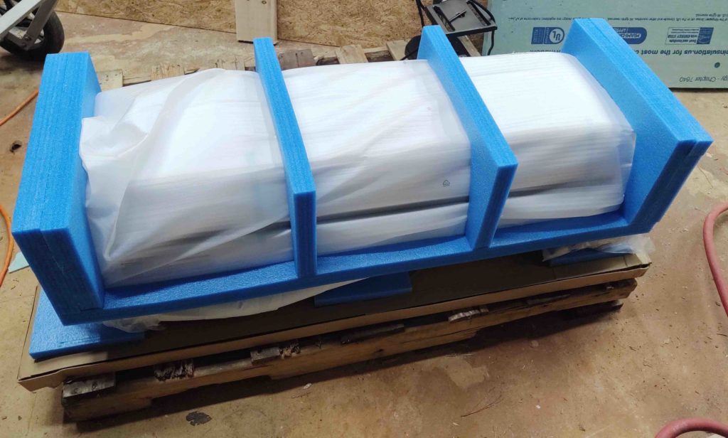
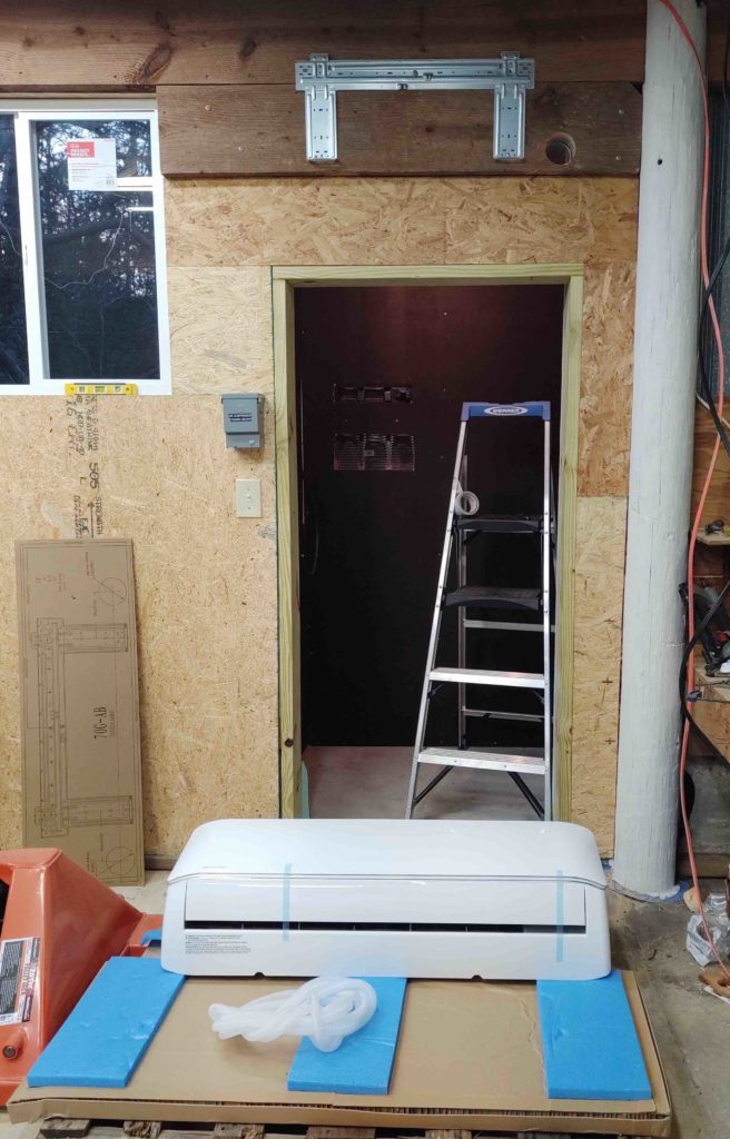
First, I finally got around to unboxing the inside unit of the mini-split HVAC system. I had drug the outside unit around back a day or so back.
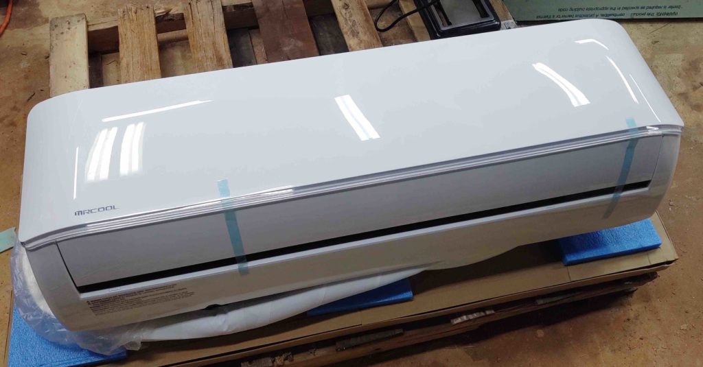
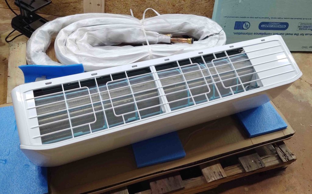
Here it is unsheathed . . .
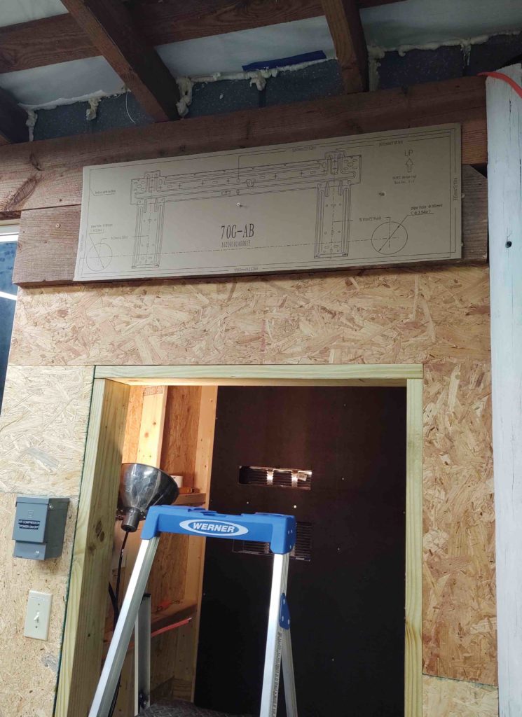
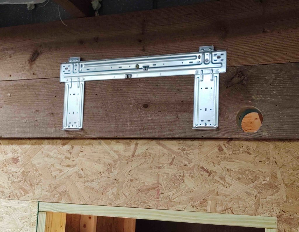
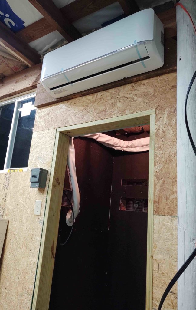
I located the mounting bracket template and tacked it in place above the door to the air compressor closet…
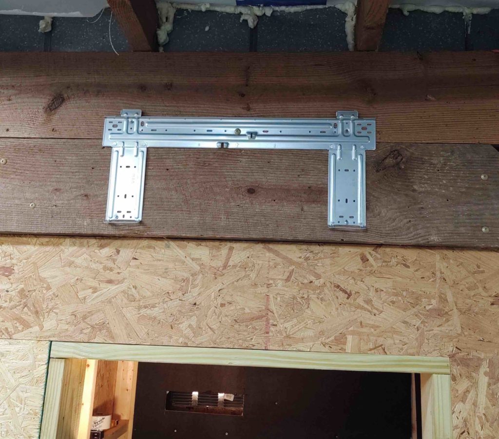
And then first screwed the mount in place, and then drilled the massive 3.5″ hole that will allow the big HVAC conduit (also, 25′ long) to pass through the wall … or shall I say the first wall.
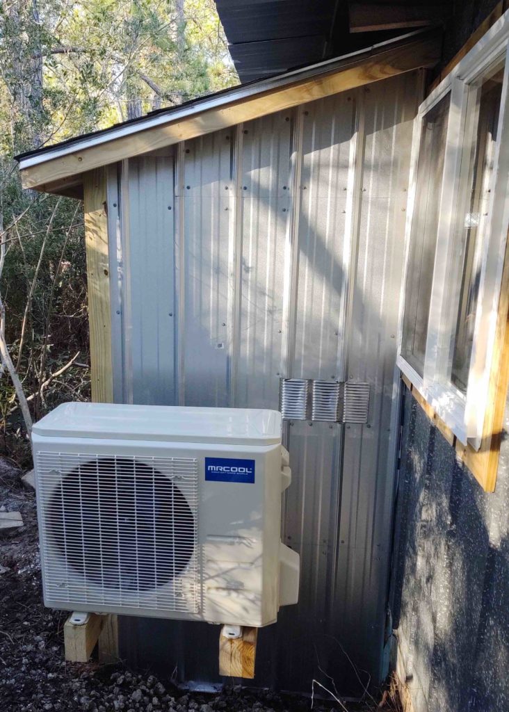
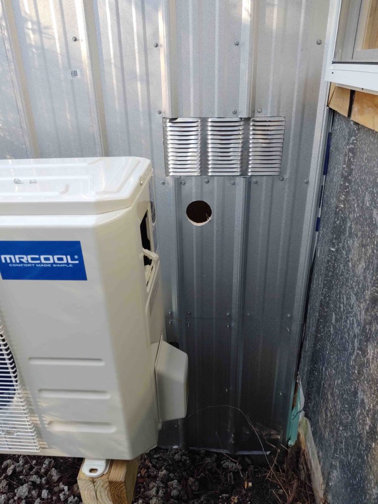
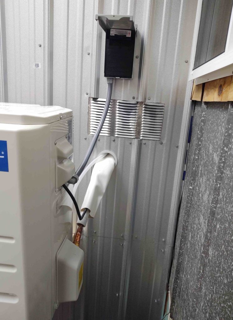
I then unboxed and mounted the massive –and quite heavy– exterior condenser unit.
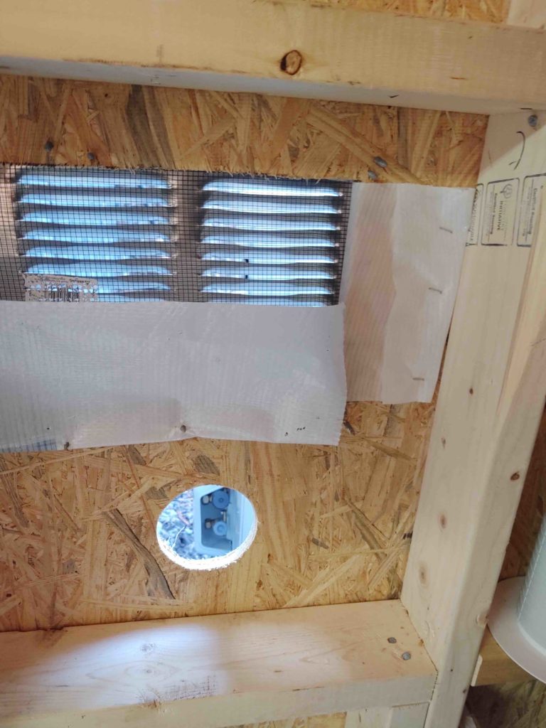
With the exterior unit in place, I then had a good bead on where to drill massive 3.5″ diameter hole #2 in the side of the air compressor closet. This was of course the plan pretty much all along.
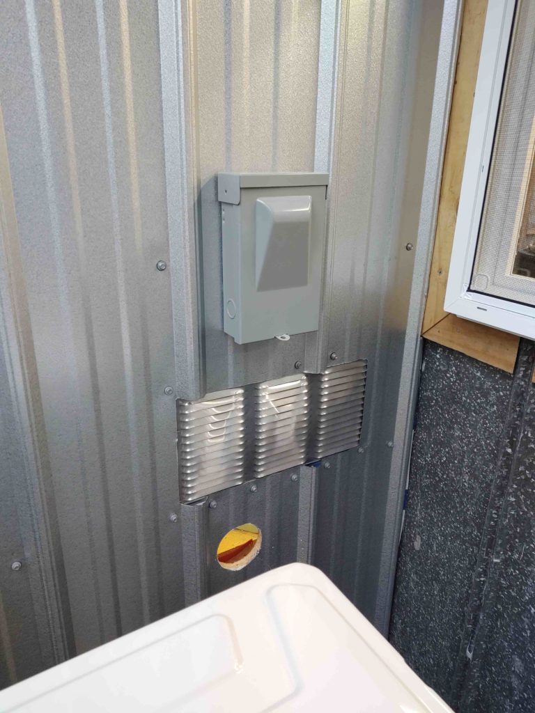
I then mounted the external quick power disconnect box, which at this point was wired up with the #10 ga cable that connects to the main power panel.
Before I could go any further with the HVAC install, I had to finish up insulating and installing wallboard (or foam) on the inside of the air compressor closet.
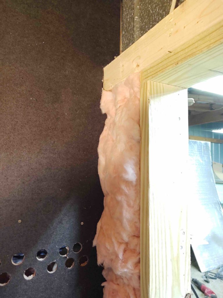
I added insulation to the inside of the shared wall, all around the compressor closet door.
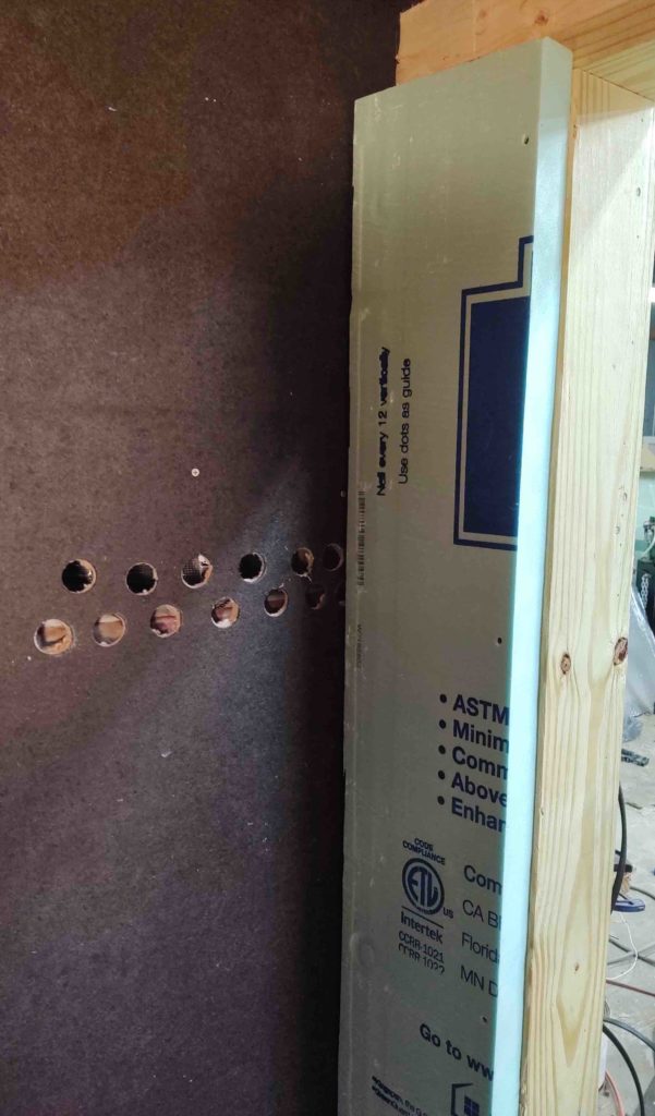
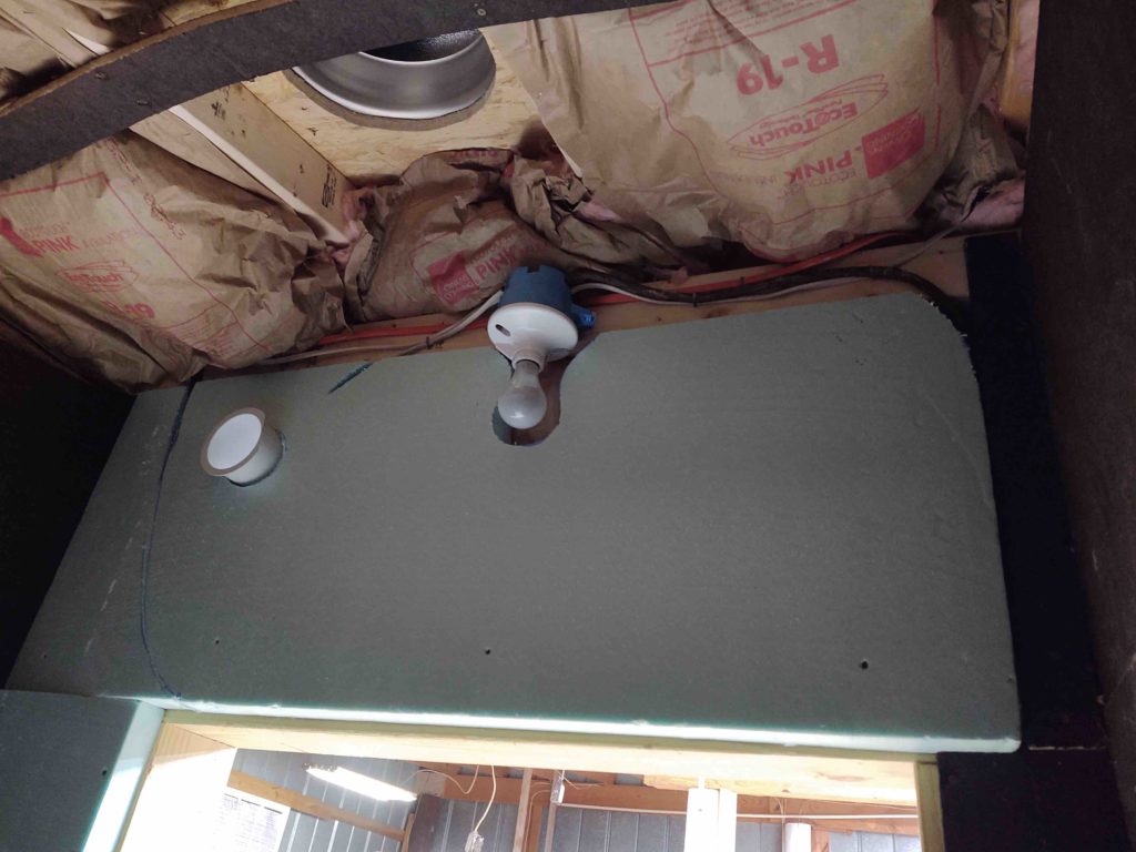
I then added 2″-thick foam to help suppress any loud air compressor noise as much as possible.
I did the same thing over the door, again adding the thick foam over the rather copious amount of insulation.
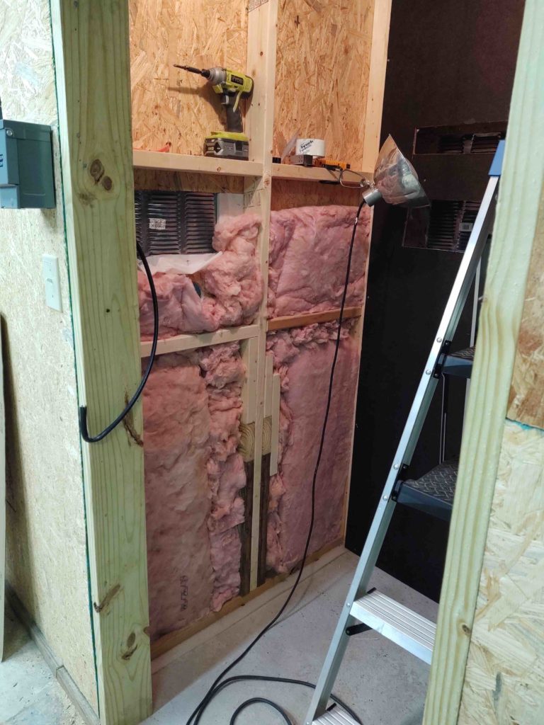
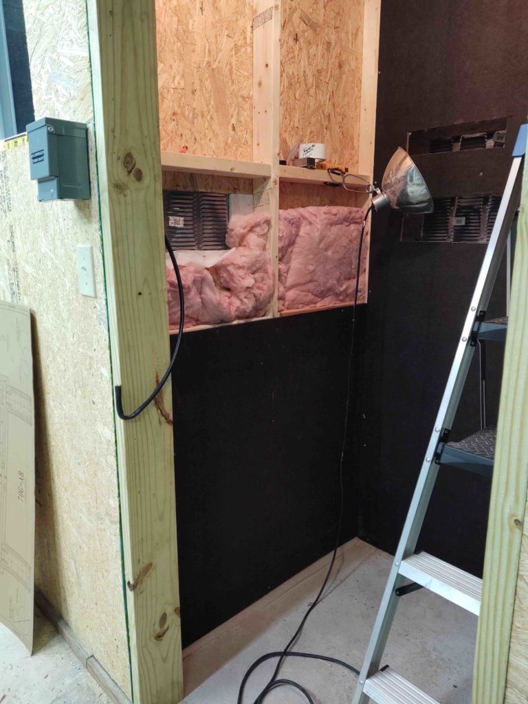
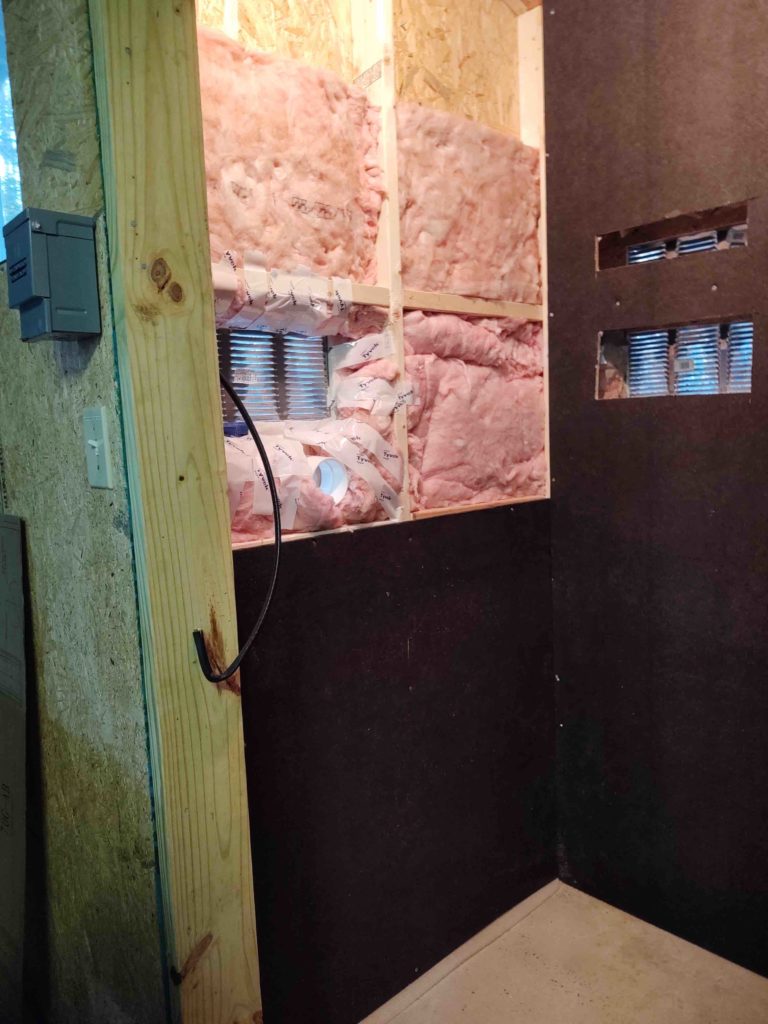
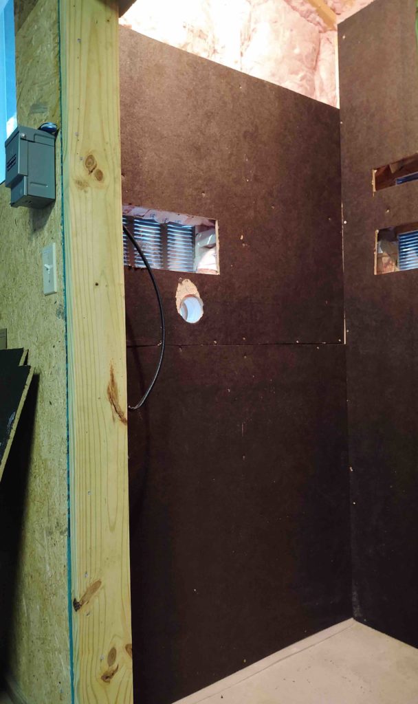
Then came the last holdout… the left wall of the compressor closet. Since it doesn’t face the neighbors (as far away as they are) I went ahead and framed this out with 2x4s vs the other two 2×6-framed walls. Thus, I used the cheaper loose insulation for this wall.
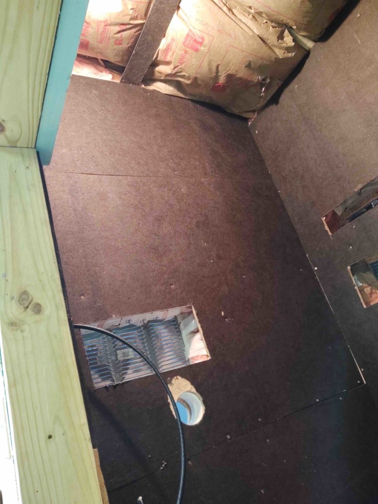
Also, just for ease I cut and attached the wallboard in 3 different segments. Here’s the bottom of 3 wallboard pieces going in.
Then more insulation and wallboard segment #2 installed.
And even more insulation and the final top piece of wallboard installed.
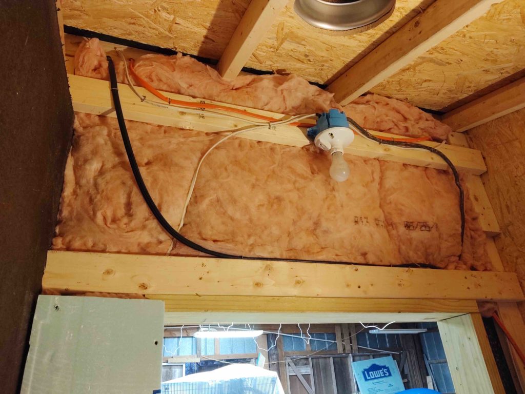
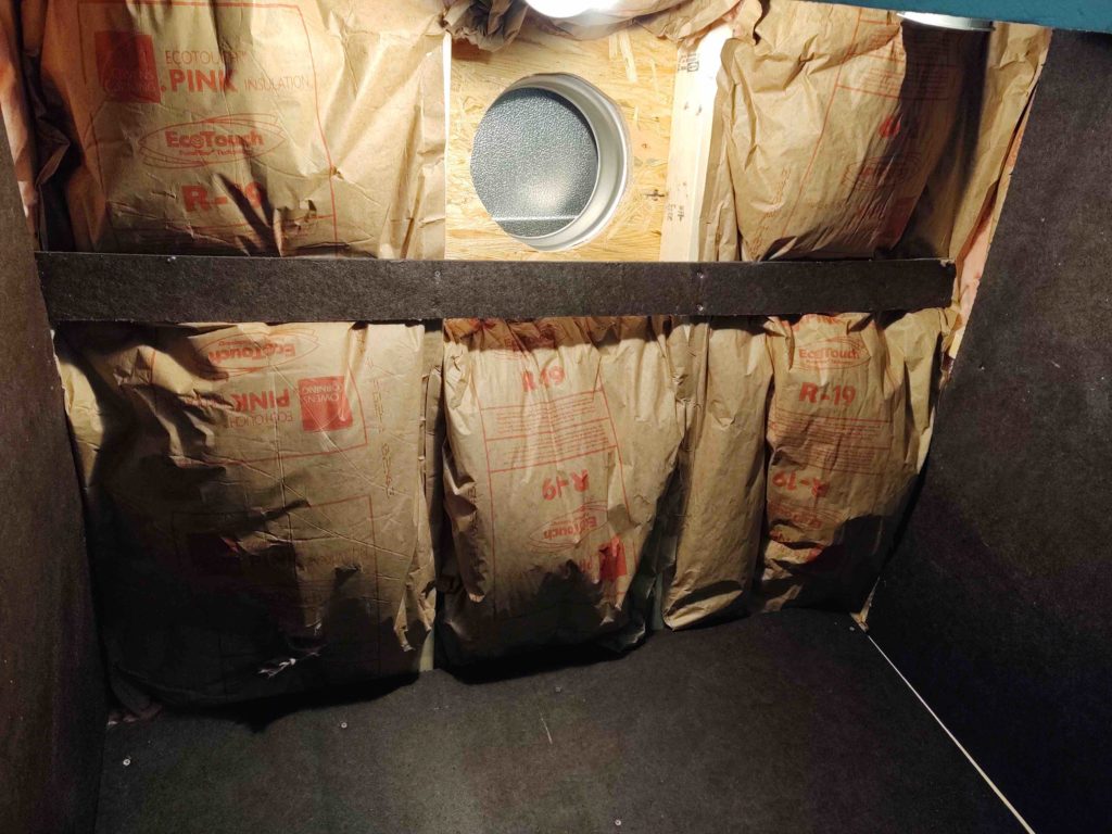
Although the roof joists on the air compressor bump-out are 2x4s, I used 2×6 insulation on the ceiling to help deaden the sound even more.
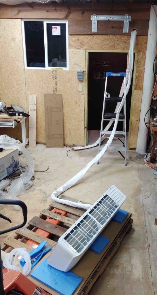
I then prepped the interior HVAC unit to be installed.
Here she is ready to go up . . .
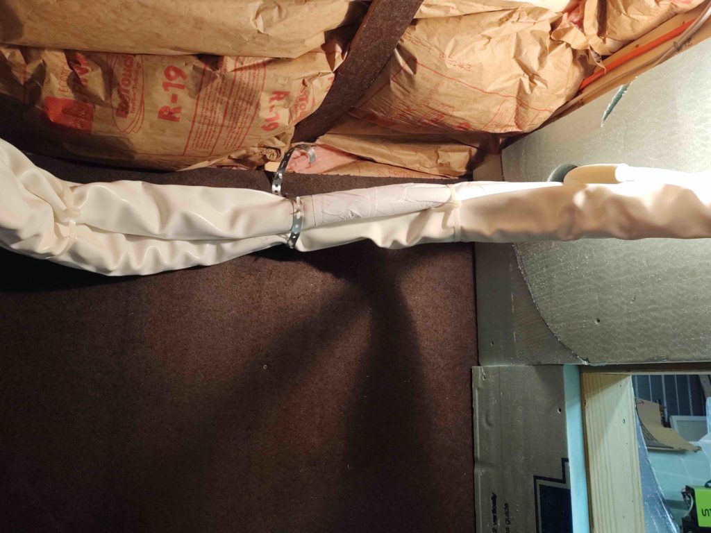
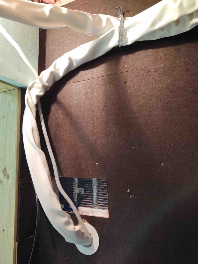
First I had to run the thick, 25-foot long HVAC conduit (2 copper tubes and an electrical cable) through the hole in the wall.
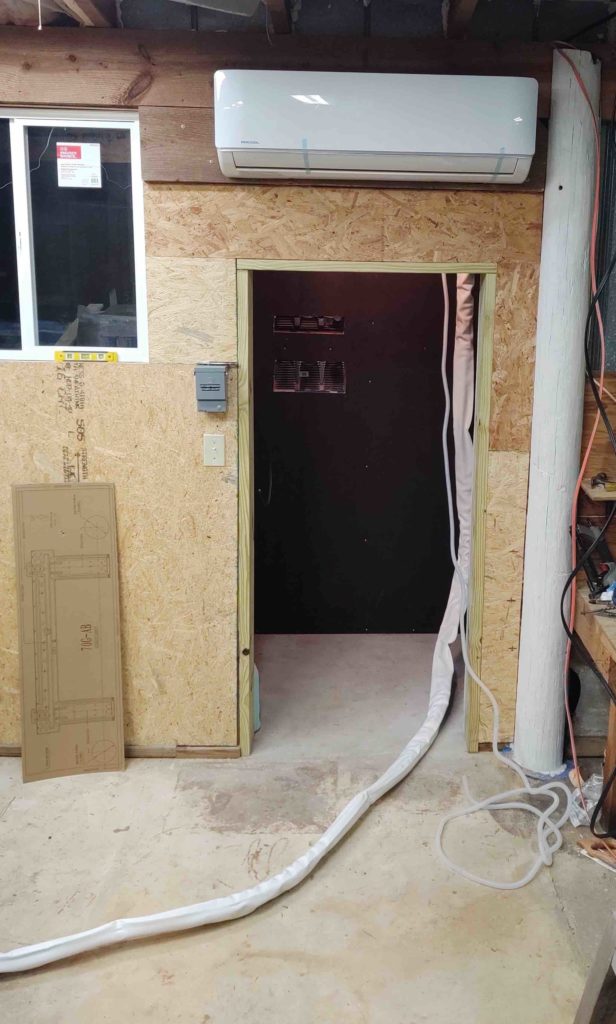
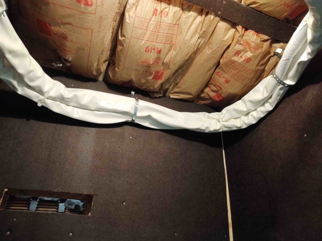
After fighting the conduit to get it through the hole in the wall for well over half an hour, I then bundled it up and attached it around the upper portion of the air compressor closet.
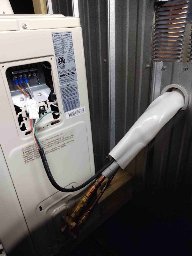
And ran the conduit out to the exterior HVAC unit (the extra white tubing is the drain line)…
Where I attached the two copper tubes to the exterior unit and performed a successful leak check.
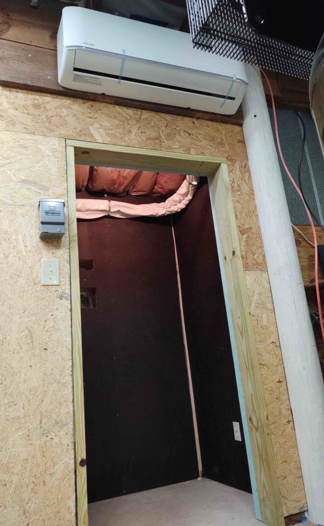
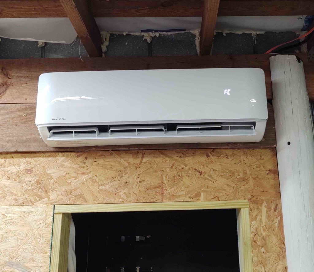
Here are a couple of shots of the physically installed indoor HVAC unit of the mini-split system.
Today I finished up the HVAC system install by focusing on the wiring, starting from the exterior unit to the quick disconnect box, and then running the cable to the main power panel at the front of the shop (I also concurrently ran the 8 ga cable for the air compressor).
After a good 30+ min of wiring in both the HVAC system and air compressor to the main power panel, replete with new circuit breakers, I then did one final crosscheck before firing up the workshop’s freshly installed mini-split HVAC system.
I’m happy to report that so far the HVAC system is powering up and working as designed, and after another leak check all looks good!

