
Before I pack up and haul my new CNC components down to NC, I needed to do an operational function test on each part to ensure it works. For each closed-loop stepper motor setup this includes the motor itself, the drive (blue units) and the associated power supply.
Since one of my power supplies was back ordered, I only have 2 on hand to test out 3 motors. I could have connected two motor setups onto one power supply, but I decided to keep it simple with one power supply to one drive and one stepper motor.
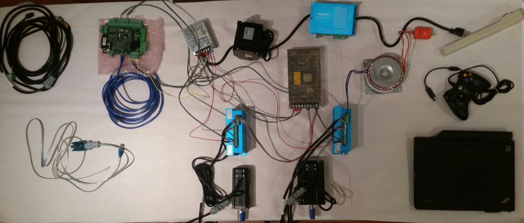
The closed-loop stepper motors I have on hand is an 8.5 Newton Meter (Nm) Nema 34 (mounting size) for the mill’s Z axis, a 4.5 Nm Nema 34 for the mill’s X axis, and a 3.0 Nm Nema 23 for the lathe’s Z axis. I also have a 4.5 Nm Nema 34 for the mill’s Y axis on the way.
I started my ops test with the 8.5 Nm Nema 34 and 3 Nm Nema 23 stepper motors. Prior to the actual ops check I connected up a data cable to the respective motor drives and changed the drive alarm circuit parameter from Normally Open (NO) to Normally Closed (NC). This is rather important in identifying any drive fault in that a NO circuit would not indicate if the actual circuit was, say, cut. Conversely, if a NC alarm circuit is damaged or cut it will result in an alarm…. clearly better (IMO) to have a NC alarm circuit.
Since this was my first go at real-world spinning of the stepper motors, it required a 2-hour period of research and digging in the manuals to educate myself after I got power to the motors to actually allow the Acorn CNC controller to control the motors.
Here’s a ~25 min video showing my efforts:
I still have the 4.5 Nm motor to test, but I think all the above is enough excitement for one evening!