Glass it!!!
I started out today by getting the first of many things curing.
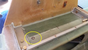
Since I will have a myriad of electrical components housed in the GIB headrest, I am completing the task I started when I populated and configured the Hell Hole before mounting the firewall. The task here is to drill a wire transit hole through the top of the CS Spare (not the spar cap area of course) by first reinforcing the sides of the eventual hole with flocro, and then create the hole.
I started by identifying exactly where the wire transit hole was going to be located. My aim was to get it as close to the front right interior corner of the GIB headrest.
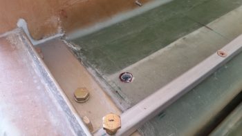
I then drilled out a good side sized hole ONLY on the top surface of the CS spar. I then dug out a good plug of foam to allow me to replace the foam with a 50/50 mix of flox and micro.
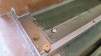
Here the flocro has been put in the hole and is curing.
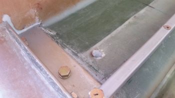
I’ll jump ahead here well over an hour into the future to show that the flocro cured and I drilled a final 7/16″ hole through what will be the GIB headrest “floor.” The area surrounding the hole will get further reinforced with the interior 2-ply BID tape that I’ll layup when I glass the headrest in place.
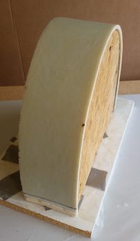
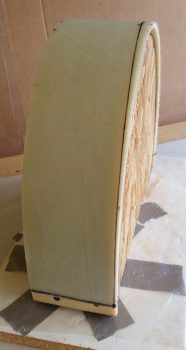
I then got to work on the GIB headrest. I pulled the peel ply and sanded the surface where any imperfections where apparent.
I then marked the glassed GIB headrest for cutting. The top depth is 3.6″ while the bottom depth is 3.9″.
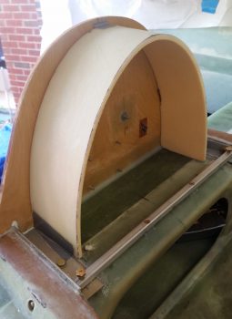
After cutting the GIB headrest with the Fien saw, I then test fitted it in place.
Not shown is my spending about an hour measuring, test fitting, ascertaining, and determining final component placement inside the headrest. One thing became quickly apparent to me, and that was no further steps could really be taken on the headrest until the inside surface was glassed.
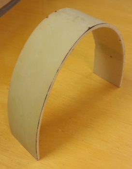
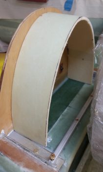
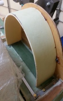
So I laid up 1 ply of BID on the inside surface of the GIB headrest, and then peel plied it. I then set the headrest back into place and taped the edges so that it was in what would be its final shape. Another view I didn’t capture on camera was that if the headrest sides weren’t kept in check, then they would splay outward. I figured an inside layup would keep the sides where they needed to be, and allow further interior component install steps to be taken.
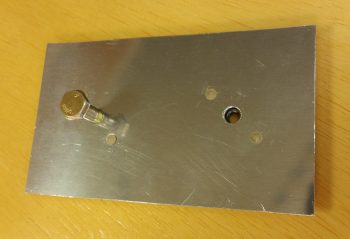
While the GIB headrest interior layup cured, I then cut the B&C recommended heat sink and mount for the SD-8 alternator’s voltage regulator. Again, according to B&C, a 0.040″ thick heat sink would do the trick, so that’s exactly what I used in the 2024 aluminum variant of metal.
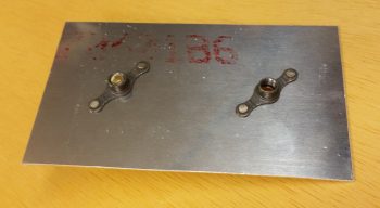
I then measured/added/riveted a couple of K1000-4 nutplates to the SD-8 voltage regulator heat sink mount for the SD-8.
Here’s the back side of the SD-8 heat shrink mount showing the nutplates riveted into place.
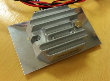
And a shot of the SD-8 voltage regulator being test fitted onto its heat sink mount. I think this heat sink mount should do the trick nicely.
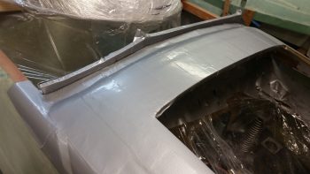
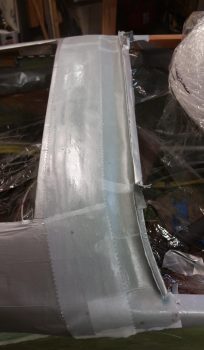
I then set my sights on the last task of the evening: glassing the aft end of the avionics top deck cover which is technically the actual glare shield.
I started by adding a urethane foam shelf that stuck out from under the glare shield sub-structure by 0.9″.
I then added a taped foam wall on the aft side that will create a lip on the aft edge of the glassed glare shield once it cures. This lip will both interface with the canopy front skirt as an ad hoc interlock and will also serve as a drip guard/block to keep any incoming moisture diverted to the outboard edges of the canopy skirt.
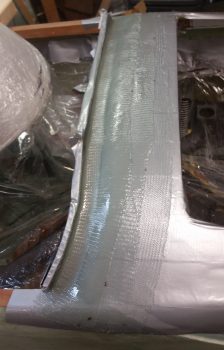
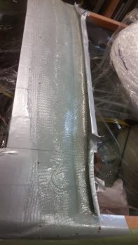
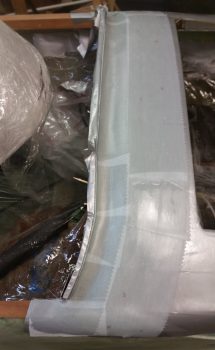
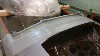
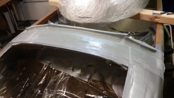
I laid up 3 plies of BID in what will be the bottom (interior) surface of the aft nose/avionics top deck cover.
My layup for these 3 plies of BID had the first ply going on at 4.5″ wide, with the next ply at 3.5″ wide, and the final ply at 2.5″ wide. My primary focus was on the aft “trough” side of the layup to ensure that all 3 plies were laid up well to create a strong glare shield, especially since it will have a structure consisting of nothing more than cantilevered glass.
Again, to reiterate, these 3 plies are the bottom/inside surface of the very aft edge of the avionics top deck cover, so more plies will be added to these as the top cover is constructed.
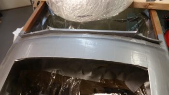
To facilitated the construction of the top cover –including the addition of more plies to this layup– I peel plied the layup.
Here’s another couple shots of the peel plied glare shield layup.
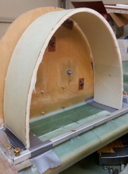
After the final glassing of the evening above, I then grabbed the GIB headrest, pulled the peel ply and razor trimmed the edges.
As per my discussion, note how the interior layup allows the GIB headrest to maintain its appropriate shape.
I then set it back into place –sans any tape at the bottom edges– to check its fit. I have to say that I’m liking what I see so far!
[Note the position of the GIB headrest wire transit hole…]
Tomorrow I’ll continue with my nose and canopy install related tasks.

