
Today was one of those big milestone moments for me in the build of this Long-EZ. Just like taking that first pic sitting inside your freshly glassed fuselage, this was one of those days that I had been wanting to get to for a long, long time. I finally got the nose gear official installed, both mechanically & electronically, and so far it’s all working pretty darn good. I’ll discuss the gear a bit later, but for now, let me start detailing my day’s work chronologically,
I started by taking 6 of K1000-3 nutplate assemblies that I made up last night down to the shop along with a scrap piece of the über dense H250 foam.
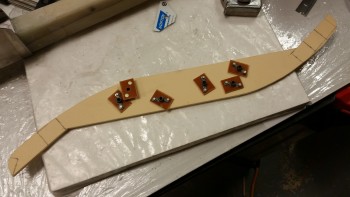
I cut rectangular pieces out of the foam to serve as a base for the individual nutplate assemblies. The odd foam piece below the row of 4 standard looking rectangles will go on the aft side CL of F28, and hang aft at a very sharp downward angle. Again, this is for mounting what is essentially a giant “T”-shaped electrical components & avionics “tree.”
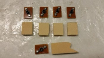
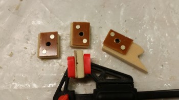
I then worked the foam pieces to allow me to embed a K1000-3 nutplate into the foam.
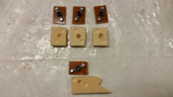
Here are the end results. Now, I had every intention of mounting these onto the backside of the F22 center strut (just forward of the nose wheel cover) and on the bottom aft side of F28, when I took a break for lunch. Reviewing in my mind that I still needed to construct the electrical component structure (I nicknamed it the “Triparagon” … don’t ask me why, but if the Avengers/SHIELD can have a building with a cool name like “Triskelion” than my electrical tree/tower/structure can have a cool friggin’ name too! Ha!), I thought why should I install these now when I can simply bolt them to the structure later, put the whole thing in place with some 5-min glue on these puppies and have all my bolt holes aligned perfectly. Duh! So, I bagged these suckers up and put them on hold.
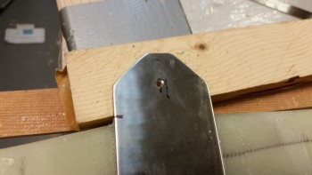
Having successfully avoided yet more work, I then moved on to drilling the outer NG3 bracket on the now cured gear strut. I messed around for maybe 10 minutes dialing in the hole location, and even though I used a hole punch my bit slid over to the left by about a 1/16th of an inch. Stainless steel being what it is, the hole seemed to magically move even further left when I used a bigger bit!
The hole I started on side #1 was definitely off center to the hole on the interior NG4 bracket. So, I left the first hole alone and since I had access to side #2 from the INSIDE, I simple drilled the other side through the first hole. I made sure that the second hole was drilled spot dead center.
I then concentrated on drilling out the second hole to about 3/16″ in diameter. Before I took this whole shabang over to the drill press, I grabbed a smaller bit (about ~1/8″) and drilled from side #2 back into the first drilled hole in side #1, this time from the inside. However, my entire goal here was to simple remove a good amount of steel so that when I drilled through side #2 on the drill press and then got to the messed up hole on side #1, there wouldn’t be much resistance to the 1/4″ bit to do its job. When I finished with this step I had a nice 3/16″ hole in side #2, and a very odd looking figure “8” or ∞ looking hole in side #1.
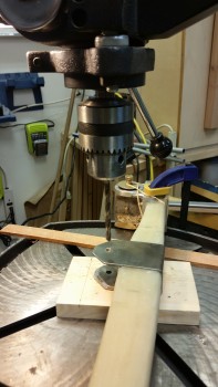
Once on the drill press, I started with a 7/32″ bit to basically ensure that the hole was centered and remove just a bit more material. I ran it down to the lower side and barely kissed the metal in the hole just to remove a bit more material. I wanted the sides of both the upper & lower holes to guide the 1/4″ bit, so I really didn’t try to do much on the lower (∞) hole with the 7/32″ bit.
After I loaded up the 1/4″ bit, it nearly slid through the first hole and made a beautiful clean (read: not jacked up!) hole on the bottom hole (the original side #1). With straight, clean holes that ran entirely through my NG3 & NG4 brackets, I was a happy man!
[One point of note: as I was installing the NG3/NG4 brackets over the 1-ply of BID last night, the brackets slid down the gear strut another 0.17″ making the total distance from the NG6B pivot to the center of the NG3 bolt to be 6.47″ total (and final). I wasn’t concerned in the least since I could always adjust the gear strut travel with the microswitches, and lower is actually better for leverage, and possibly strength(?).
After reinstalling the nose gear assembly, I made the requisite nose gear test video to make it official!
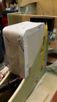
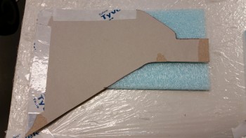
I then started designing my 2-part NG30 cover. Here’s the aft part that I came up with using scrap cardboard as the build material to construct the mockup.
I’d like to point out that the biggest reason for me covering the NG30 nose gear box is to keep cold air from rushing into the cockpit. However, another huge reason is that it gives me a platform to hang & mount a bunch of stuff all over to help organize the front nose area. I think that by designing the right NG30 cover I will really optimize the space I have available for mounting all my forward mounted components. In fact, in the pic below you can see the AEX module mounted into the aft area of the NG30 cover.
I pondered for a good while on how I was going to construct the aft NG30 cover. The front NG30 cover will be fairly easy since it’s essentially a 4″ x 6″ flat plate with screw holes.
Since I had very close to what amounted to be a basic box, I didn’t want to pull the crappy, messy urethane foam out to start carving away. I had simple lines here and the more I thought about it, the more I came to the conclusion that I needed to construct this cover in steps, first of all, and use some foam in the process. I would love to have a 3-ply BID cover with no foam, but I’m not going to A) remove the nose gear actuator to fill the area with foam to carve, or B) fill foam in around the nose gear actuator to carve, since there’s really not that much room around it to begin with.
As I was digging around for possible solutions, I ran across this foam piece in the closet. I’m pretty sure that this scrap piece was a spar cap cutout. It was maybe a 1/4″ thick and I thought this would surely do the trick.
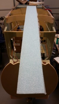
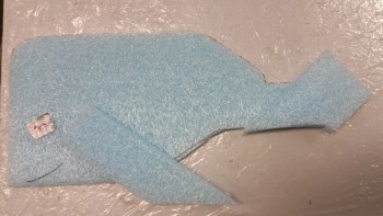
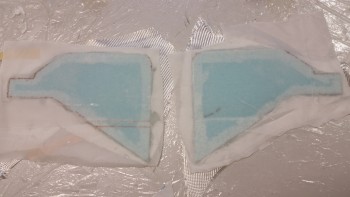
I cut the blue foam piece to width to match the total width of the NG30 cover side panel. As you can tell from the pic below, I was going to have to micro two pieces together to get one side panel.
And then guess who stopped by? That’s right! Why it’s Banarbas (aka “Zippy”) the Whale! haha! (Sorry, couldn’t resist!)
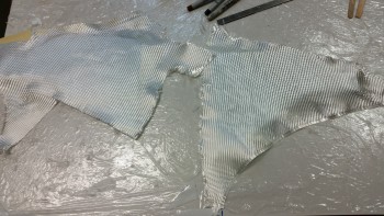
I grabbed a couple pieces of scrap BID and ensured that one per side fit.
I then laid up 1-ply of BID on each side panel of the NG30 cover. I only used one ply because a lot of phenolic plates, etc. will be embedded into these NG30 cover sidewalls, so at least 2 more plies of BID will be added to this 1-ply of BID.
Also, you may note that I only micro’d the edges of the NG30 cover foam side panels. The reason why is that I’ll keep a good majority of the edge foam throughout the cover construction since it will in fact be corner foam as the cover gets completed. However, the majority of the foam in the middle ‘field’ areas will get removed.
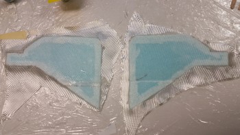
Since I will be adding subsequent plies of BID, I went ahead and peel plied both NG30 side panel layups.
Tomorrow I’ll attempt to complete the construction of the aft NG30 cover. Once the NG30 cover is complete, I’ll start working on the glassing in the nose side walls.