
Panel & Cockpit Planning
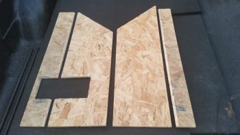
20 October 2016 — I’m essentially reverting back to the very first week of this project and slowly cutting all the pieces for a front seat, instrument panel & avionics bay mockup, or simulator, of my Long-EZ (See my Initial Project Planning page for an idea). This will allow to test locations of instruments on the panel, for both actual spacing & location preference, and also will allow me to work through the manuals with the instruments powered up in front of me so I can input all the settings in the actual cockpit environment. Serendipitously, I now have both an Infinity stick and a spare throttle quadrant to use in “the Sim.”
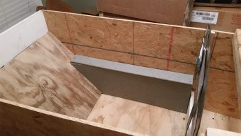
Since I have most of the pieces cut already, the main parts that were missing were the armrests. Since I reconfigured my outside shed, I know have access to my router table and it still has the round-over bit that I used on the real armrests… and still set at the exact same position! So I cut these pieces, rounded them over along the top edge pieces and then notched the right side armrest for the control stick. This will be a project for when it gets super cold this winter, or snowed in, etc.
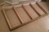
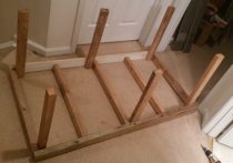
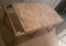
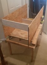
10 March 2017 — So my latest mini project was to assemble a bunch of pieces of wood that I cut late last summer to create a cockpit mockup & simulator to allow me test the ergonomics, placement, switchology and operation of my avionics and instruments. This harks back to my original fuselage mock-up to check for how the plane would feel in its stock dimensions (remember, I widened the cockpit 1.4″). Now, this version will enable me to mount all my current avionics, plan for new ones, and give me a really close estimate on final wiring requirements for all my panel components. This latter reason is why I made this cockpit simulator to allow for the installation of the Triparagon.
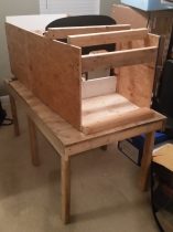
When the Triparagon is installed I’ll wire up the panel and fire up the components not only to do a good ops check on them, but also to configure them in the panel. Also, this cockpit mockup will also allow me to finalize any wiring required on the Triparagon.
You may note looking at the pics above that the wood looks a little ratty and non-uniform, and you’d be right! So far, this entire mockup has been made of completely scrap wood.
Below you can see the right side armrest. Since I won’t be mounting my second Infinity control stick into the actual airplane, it will get mounted here (although I probably won’t wire it up) into the right side armrest.
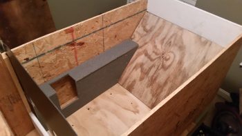
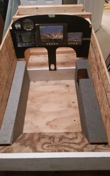
On the left side I’ll use the cockpit mockup to figure out exactly where the throttle will get mounted, and how everything else will be configured on the armrest. You may note the different gray colors of the two armrests, which is me using these as paint color swatches to help me decide the color (or colors!) of my interior cockpit paint.
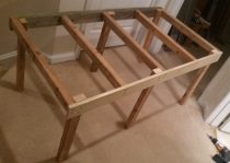
I’m accomplishing this cockpit simulator mockup construction in 6 phases, and right now I just finished Phase IV. Phase V will be cutting and installing the avionics in the instrument panel, and Phase VI will be configuring the two separate armrests with the control stick and throttle.
As you can see, once I get this guy up and running, I’ll be able to test out different component and switch locations no matter what’s going on with the actual cockpit. In addition, this mockup will really come in handy while I’m sanding away on my Long-EZ in prepping it for paint, all the while ensuring that my eletro-whizzies remain dust free!
[Note: I didn’t end up really using this a lot since when it came time to make a panel mock-up, I opted to do it in a simpler “panel-only” version somewhat like Marco had done for his panel upgrade. It was much easier to get in and around the panel components for wiring, etc. Not to say that this mockup above didn’t provide some really good data.]
•••