
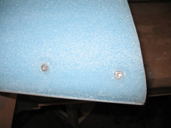
Today I removed the bolts/taped washers from the baggage pod threaded inserts & Dremelled the edges flush with the wing foam surface.
I then removed the remaining peel ply strip from the TE & it wasn’t that bad (I’m lying! Removing TE peel ply sucks!)
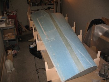
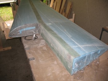
I micro’d in the Nylaflow rudder cable conduit & kept it in place with toothpicks about every 10-12″, after micro’ing in my ~5/16″ x 4″ repair piece into place as a channel “false floor” for the Nyloflow as it traverses the front aileron cavity. I’ll cutout any excess foam once I cut out the aileron and start working in the aileron channel.
I also tacked on a 65″ x 1″ strip of peel ply at the aileron’s top “leading edge,” on the wing side (essentially above the aileron to wing junction, only on the wing side).
 I then vacuumed the entire wing & finalized all the preps for glassing the top.
I reinserted the big block of foam back into the Inboard wing root end (BL 23). Before I reinserted it, I wrapped it in saran wrap so the repair micro wouldn’t fasten the removable foam to the wing, and thus make it NON-removable (aka bad!). I reinserted the broken piece, but will wait until I actually start glassing the wing to micro it in.
I checked the micro holding the Nylaflow rudder cable conduit in place, and it had not yet started to get tacky, so I took a break while the micro cured a little bit more. I didn’t want to layup the top glass just to have conduit trying to escape its micro bonds and thus deform the wing surface layup.
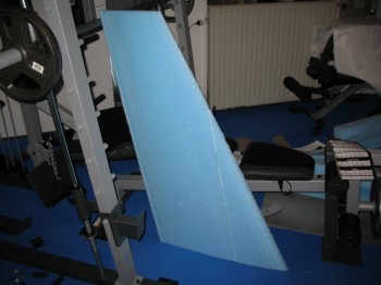
In the meantime, I went downstairs and micro’d the Right upper winglet pieces together.(there were no more Left wing sections to micro since they were all bonded together–in their respective sections FC1 thru FC5–and ready to be assembled.)
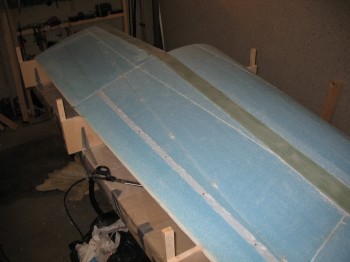
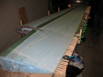
When I returned to the shop, I took a good look at the wing & used my flat sanding board to clean up the wing surface, especially at the joints. I wanted to ensure a smooth flow over the wings, which honestly is much more important on the wing upper surface than it is the bottom. Of course, having re-sanded the wing, I had to vacuum the entire upper wing surface again.
I micro’d the foam joints & the spar cap edges (no micro goes on the spar caps, just wet epoxy!) with dry micro. On the large areas of plain foam (what I call, “the field”) I used wet microslurry.
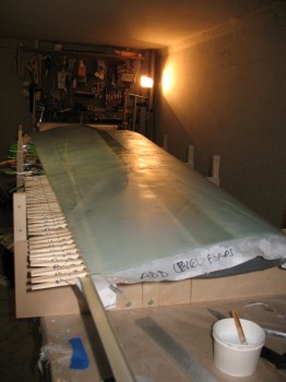
In laying up the UNI on the wings I used up all the slow hardener I had prepped in my 2 squeeze bottles. The transitions looked good, and at only ~70°F the epoxy seemed to be curing fairly fast. I added the triangular BID reinforcement at the Outboard end of the wing & covered it with peel ply. I then glassed a staggered 3-ply UNI layup over the Inboard wing bolt extrusion, that covers the extrusion and then folds over the edge of the wing and is laid up on the top front corner of the wing surface as well. Also, I clamped the TE with a long piece of L-shaped aluminum to ensure the TE was as straight as possible.
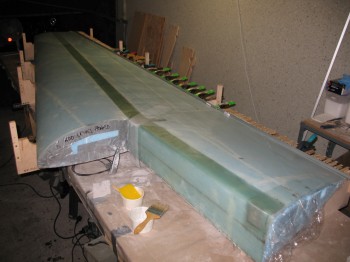
I peel plied the “V” that straddles the upper wing bolt access hole, and as you can see, wrote out a couple notes admonishing myself not to forget the wing level board that must be bondo’d to the top at 0° incidence, so that the wings can mounted at the correct incidence angle.