I would love to say that I got some really cool layups in today, but I can’t. Today was all about prep. And I mean I literally spent about 10 hours prepping a myriad of nitnoy things to get chapter 8 knocked out.
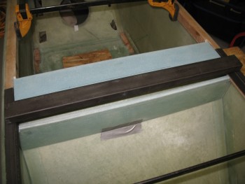
I started by spending about a 1/2 hour sanding the face of the seat back shelf so that it was as straight & level as possible. Sometimes I feel more like a sculptor more than an airplane builder! Once it was level, and I had it in the fuselage, I just wasn’t sold on the sharp edge that would make up the corner of the back of the seat and the new seat back shelf (headrest base) that I was working on. I decided that I was going to radius that corner with a 3/16″ round-over router bit.
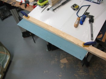
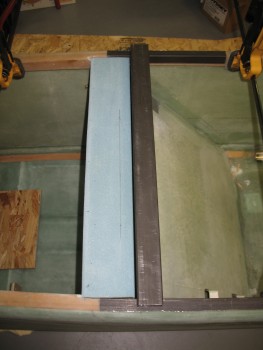
I clamped the piece to the work bench, and due to the edge being so sharp & the angle so great, I had to use a guide to keep the bit at the right position on the cut.
Here’s a shot of the aft side 3/16″ router cut on this piece.
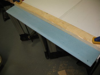
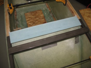
I then radiused the front edge 1/8″.
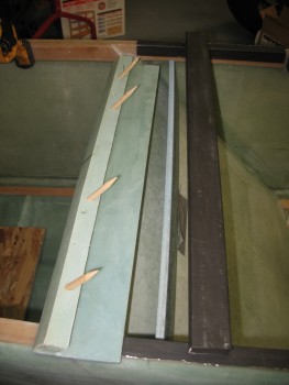
I mocked it up to check out the look of the radiused edges, and was happy with the results.
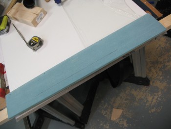
After I checked the seat back piece, I then radiused the top edge of the lower seat back piece using the same 1/8″ bit I used on the front of the piece above.
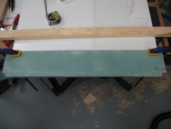
Here it is after I routered the edge.
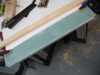
I then added that piece into the mock-up.
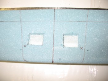
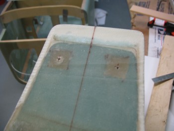
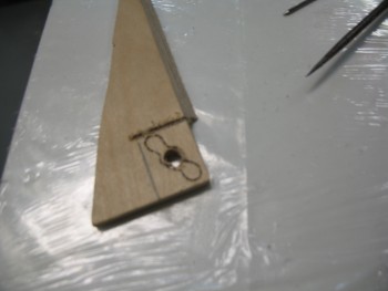
I turned my sites on getting the aft hard points for the headrest prepped so it’s ready to glass either later this evening, or tomorrow. I measured out and marked the positions of the 2 aft headrest bolt holes.
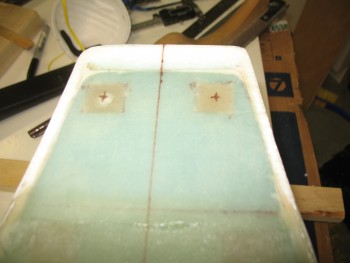
I then drilled the holes.
Next, I started making the hardpoints that will sit opposite these aft bolt holes in the headrest. These hardpoints will be mounted in the foam that makes up the seat back shelf, much in the way that the original Long-EZs had their seat belt hardpoints configured.
I started by grabbing some 1/4″ Birch Plywood to use as my hardpoints. I’ll also be using the K1000-3 nutplates. I marked up the first hardpoint using the K1000-3 as the determinant for my dimensions.
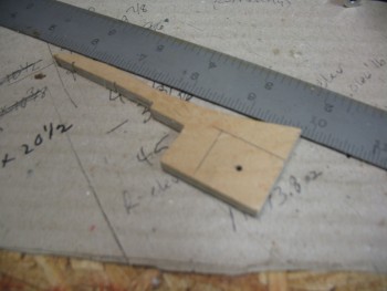
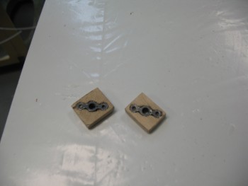
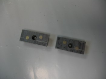
After I drilled the center hole large enough that the stem of the K1000-3 nutplate would fit inside, I traced the nutplate and used my razor knife to make a pocket for the nutplate to fit in so it will sit flush as its embedded inside the foam mounting point.
Here’s the 2 nutplate assemblies that I’ll embed so that they become the aft hardpoints for the headrest assembly to bolt to.
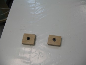
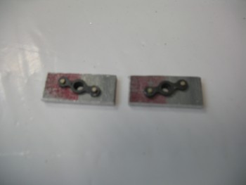
And the reverse sides. BTW, I intentionally made these slightly different sizes in order to tell them apart and not get them confused during the installation.
I set the headrest’s aft hardpoints aside and made up 4 dowel guide pins to help the new seat top with the existing seat, especially as it’s curing.
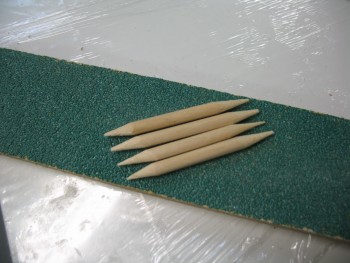
Here’s a picture of them installed in the new seat top piece.
With the seat top ready to go, there was still something I needed to complete before the seat top gets glassed in permanently. The roll bar will be bolted in from the inside of the longeron out using 1/4″ bolts at the very front of the side roll bar longeron rails, and at the aft end of the rails. In the middle area, where the new composite seat assemble will be built, I won’t have access to install a bolt there, since the entire area will be encased with the seat back assembly. So the third, and middle hard point for the roll bar will be a 3/16″ screw that will be installed from the top to the bottom of the longeron. Since the longeron isn’t that wide, I will be using a 3/16″ screw to ensure a lot of strength, but also minimize the cross section of the hardware installed in the longeron.
Again, since I won’t have access to that area, I can’t secure the screws with the traditional nuts & washers. For this endeavor, I’ll again use a K1000-3 nutplate. However, instead of mounting it into wood, I’ll be riveting the nutplates to 1/8″ 2024 aluminum backing plates.
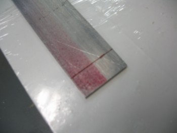
Here’s the nearly finished set.
And from the other side.
Tomorrow I’ll shape the edges & then Alodine the aluminum before riveting the nutplates to the pieces.
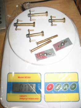
I also spent a decent amount of time figuring out my hardware requirements for the rollbar assembly. I was curious about the weight of the hardware, so I threw them all on the scale: 0.17 of a pound. Not bad!
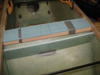
With that out of the way, I started mocking up the headrest on the seat back shelf so I could determine exactly where the headrest hardpoints needed to go.
I measured, eyeballed, laser-sited, and double-checked the hardpoint positions before pulling the trigger on marking them up.
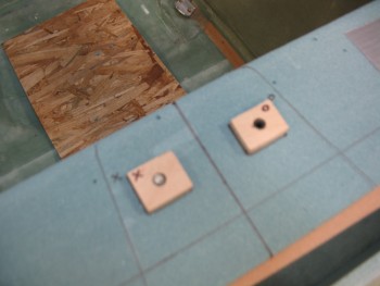
Here’s a shot of the headrest hardpoint positions prepped on the seat back shelf.