I started off today cleaning up the layups I did yesterday on the seat back shelf/headrest base & the lower seat back 0.7″ add-on piece.
I then pulled the peel ply on the lower seat back piece & cut out 2 small rectangular pieces to fill in the notch on each upper corner that originally allowed for the piece to set up tight against the longerons (basically the stock style seatback piece that gets glassed to the seat back at the lowest point of this whole endeavor).
I then went scrounging through my old BID pile to find 2 acceptable pieces of BID to use for these next two layups. I’ll pre-preg the 1-ply BID for the underside of the upper seat back shelf where it joins the gap fill piece that will make up the new top of the seat (replacing exactly what I cut away a couple of years ago!).
I started by micro’ing all the pieces (4 total) of the lower seat back, covered it with saran wrap and then weighed it down to hold it’s shape (you can see it in the background below covered with a veritable smorgasbord of chemicals!). I had already wetted out the pre-preg when I started on the lower seatback piece, so I then used the small amount of leftover micro & added a boatload of flox to it to make up the fillet for the seat back/gap fill piece.
I did a final prep on the 1-ply BID pre-preg, cut it to size (2″ BID tape) & then laid it up.
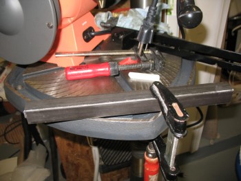
Here’s the final layup, peel plied and curing.
With the micro on the lower seatback piece significantly more gummy, I laid up 1 ply of BID on what was 4 completely separate parts just a half hour ago.
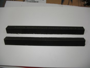
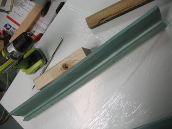
I then went into a completely different direction, breaking out the 1 x 1 inch square 4130 tube that will serve as the side rails for the roll bar assembly. I know a fair number of my compadres use a rectangular piece to start so that they get a full 1-1/2″ coverage on the entire inside of the longeron. But I really want to save as much weight as possible on the rollover assembly (ok–everywhere) and lopping off a 1/2″ strip of 4130 steel on a total run of about 24″ will help quite a bit. I may be somewhat more sensitive to saving weight on the rollover where I can–without compromising safety–since I’m adding well over a pound of weight into the mix by actually having a headrest.
The advice I got from Marco on cutting this 4130 steel was to use my table saw with a cutoff wheel, which I will most likely do for the 4130 steel that I’ll be using for my engine mount extrusions (vs 2024 aluminum… at least on the top mounts). With it being a very windy day, and with the amount of energy I have to expend on pulling my table saw out of the external shed, change the blade, etc. I chose to go into true experimental mode (read: lazy) and use my Dremel Tool with a cutoff wheel to rip the square tube into 2 pieces of 4130 angled steel.
I know I’ll be shaping & cleaning up the edges as the rollbar build progresses, so I wasn’t overly concerned about some slight waviness in my cuts.
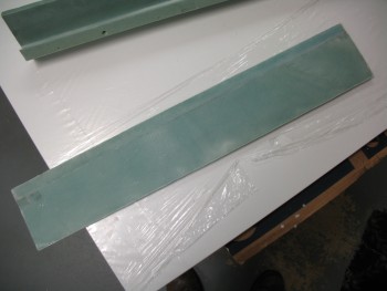
It took me about 20 min & 3 wheel changes to cut 24″ of 4130 steel. And here’s the final product(s):
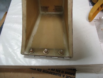
 Moving on . . . since my MGS 285 slow hardener was taking it’s sweet time on curing, I decided to go ahead and install the screws on my rollover assembly. I have a bunch of the same 82° Stainless Steel Allen head screws that Mike Melvill used in doing a major makeover on his Long-EZ years ago. He gave the part # in a CP, so I ordered a bunch of them thinking I would use them as he did. Well, tonight was night!
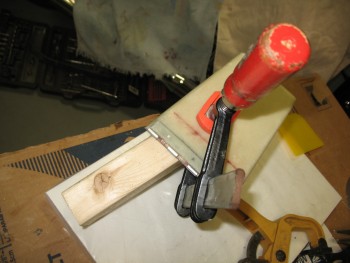
I clamped a piece of scrap wood behind the glass to prevent any blowouts from drilling the holes. Each hole was a 4 step process: pilot hole bit, ~1/8″ hole bit, #10 hole bit, and CS bit.
Here’s the final drilling on the top headrest piece hinge attach holes.
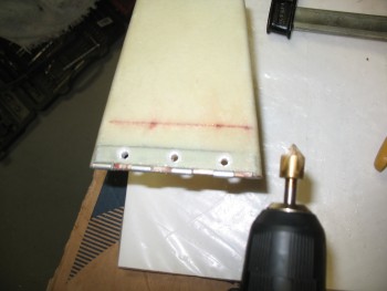
And no blowouts on the inside (a lesson I learned by NOT following the plan’s guidance while drilling some of my NG30 screw holes…. luckily Marco quickly sent me page & verse denoting where I had violated the law of Burt … again, live & learn!)
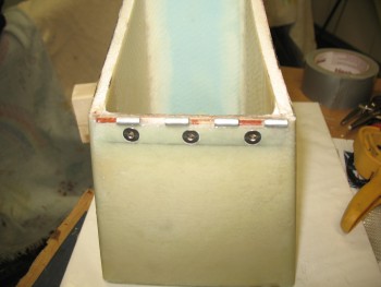
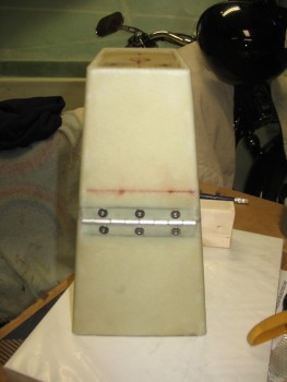
 And here’s the Melvill screws installed. Not bad looking at all!
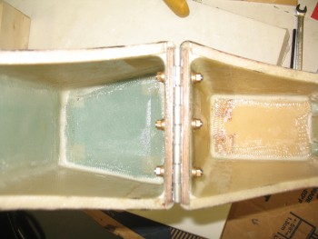
And from the inside . . .
And then the base of the headrest . . .
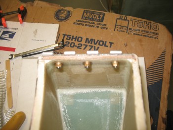
And all together!
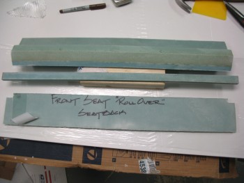
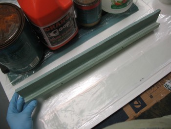
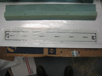
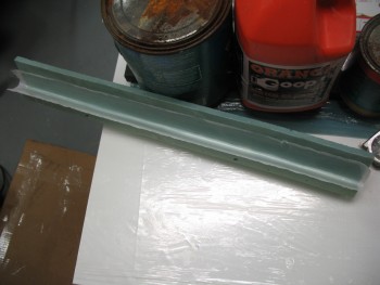
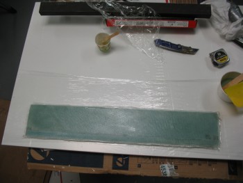
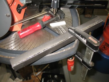
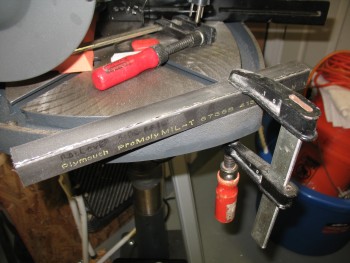
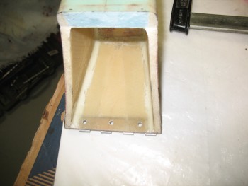
Here’s a shot of the finally cured & cleaned up seat back & spacer piece.
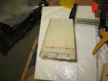
Also, a shot of the lower seat back, also cured & cleaned up.
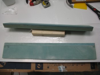
And now for this evening’s finale . . . mock-ups! I started by placing the seatback shelf in its position on top of the current seat (whose straightness was significantly enhanced by the post cure).
 I then added the headrest.
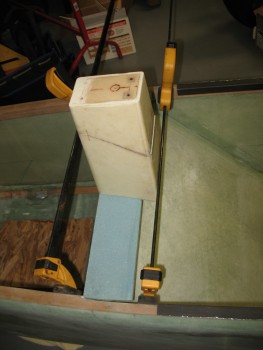
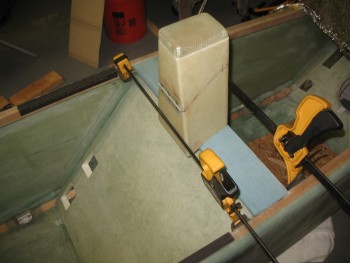 And a shot of the lower seat back in its approximate position. Ironically, I will most likely have to notch this piece as well on both sides for it to fit under the longerons.
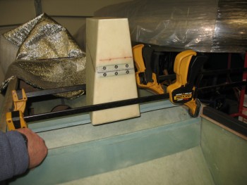
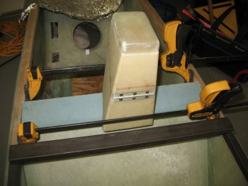
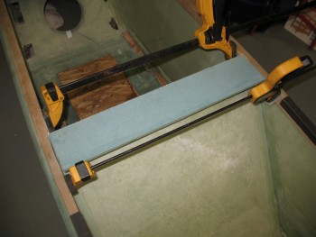
I thought I would also show a few pics of the rectangular rollover cross bar with the the roll bar in its approximate position.
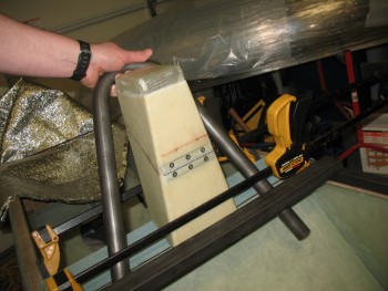
A head-on shot. Of course the cross bar will sit further aft, about where the expander is currently positioned.
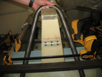
And the final shot of the evening focusing on the rectangular rollover cross bar & the headrest sitting on the seat back base.