Today I started out by laying up some reinforcement BID on the longerons, which will lie directly inside the roll bar side rails. I wanted to add some reinforcement to buttress up the longerons to give the roll bar bolts just a little more to grab a hold to.
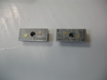
Now, to back track just a bit. I was planning on glassing in a nutplate riveted to a piece of 1/8″ 2024 aluminum (see pic below) under each longeron to allow me to install a countersunk screw in the center-“ish” position on each of the side rails as one of three attach screws/bolts on each side of the roll bar. However, as I was cleaning up the underside of each longeron to ready the floxing/glassing in of these nut plate assemblies, I realized that the original flox fillet in the corner between the fuselage side wall and the underside of the the longeron was keeping the aluminum plate from sitting level. After messing around with it for a bit, it was clear that the nutplate assemblies would only sit slanted with the underside of the longerons in their current state, no matter how clean the undersides of the longerons were.
I also realized & had accounted for the fact that positioning the roll bar side rail middle mounting hole was going to be a bit difficult to align with the longeron hole/nutplate assembly since the side rail would have to be drilled at a later point, while the longeron would have to be drilled prior to mounting the nutplate assemblies to ensure they were aligned correctly with the mounting screw hole. Of course it’s always easier to get all the associated components together, ensure all is aligned and then drill it all in one shot. This method is definitely what I preferred to do.
So I went with Plan B, which involved a 2-step process for the center side rail mounting screw. First, I would glass in a small 1/16″ thick phenolic shim, 0.35″ in width (half of the longeron’s 0.7 width). The phenolic gets glassed in on the interior underside of each longeron at the point the nutplate insert will get installed, with the inboard edge of the phenolic shim even with interior edge of the longeron. The resulting gap behind the phenolic shim then gets filled in with thick flox, and voila, a straight bottom surface is created on the longeron to mount the nutplate assembly AFTER the side rail is in place, and both the side rail and longeron can have the middle screw mounting hole drilled simultaneously. Once the side rail and longeron are drilled, I’ll install the mounting screw from the top to secure the nutplate assembly on the underside of the longeron, at which point I’ll flox & glass the nutplate assembly in permanently.
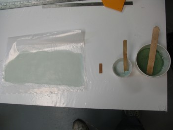
So to start, I pre-pregged 2 plies of BID.
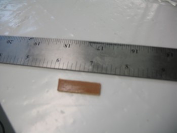
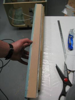
Here’s one of the phenolic shims. The pic’s not the greatest, but you can see a little bit of the quick sanding I did to rough up the surface a little for better bonding to the epoxy.
And here are the side rails reinforcement layups.
Ok, now that I wrote the novella above to tell the story for two mere simple layups of 2 plies of BID on each longeron, I will regale you with yet another tale. The minor issue that I wanted to resolve was that I wanted access to the interior side of the seat back top assembly. Primarily for two reasons:
1. Construction of the seat back assembly
2. Storage
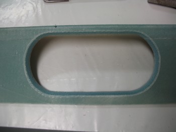
I’ve been bantering this around in my mind for the past few days, and was thinking about cutting out a rectangular hatch on the lower back support, and possibly hinge it and secure it with some type of latch. Well, I had an epiphany and decided to not only hold true to K.I.S.S. but save a little weight and go traditional in keeping with Burt’s style. Thus, I would simply cut an oval shaped hole, radius the edges and call it a day! This gives me the access I want, saves a little bit of weight, and looks kind of cool (I think!).
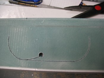
I grabbed a piece of scrap wood and threw some duct tape together to create a seat back hole mock-up.
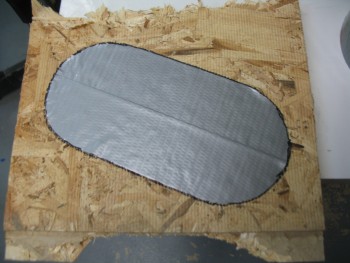
After I traced out the tape & before I cut out the oval test access hole, I thought I should start smaller and work my way out. I drew another hole outline about 1/4″ inside the first one and used this as my cut line.
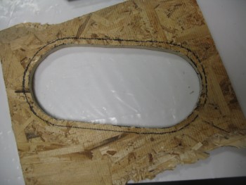
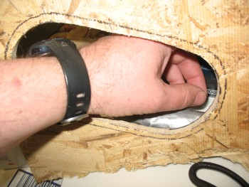
Then I tested the available access space. Since I could actually move my hand in & around very freely, I narrowed the height of the hole by another 0.2″ and shaved about the same off the width.
I took my finalized dimensions upstairs and created a template on graph paper, cut it out and had my new access hole outline template ready to go.
Back in the shop, with the lower seat back piece in hand I knocked out some clean-up tasks first by trimming the rear glass overhang–at the aft side of the 1/4″ yellow foam–down to 1/4″ to match the strip of yellow foam that will connect the upper seat back shelf assembly to this assembly. I also sanded it down for a good gripping edge since I had forgotten to peel ply this edge (yeah, what gives?? I love peel ply!)
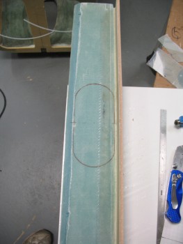
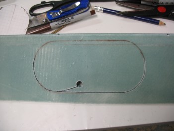
Then I used my newly made template and traced around it on the INSIDE of the seat back, since that was where all my clearance issues had to be accounted for.
I drilled a starter hole & then used my jig saw to cut as much as I could on the back side of the lower seat back assembly before my blade guard hit the yellow foam piece.
[Note: You may notice some air bubbles in the micro fillet at the corner of the blue and yellow foam. I’m fairly certain that this was caused by my having to re-position the yellow foam a number of times to get it to line up 90° to the blue foam. I would stipple the air out with a brush, have to tweak the position of the of yellow foam (since I wasn’t using a jig) and then the bubbles would reappear. I was more concerned about angular positioning than the bubbles, since I’ll simply inject those later].
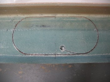
I then flipped it over, tweaked the outline to ensure it was straight and finished cutting out the hole.
After the hole was cut, I sanded down the edges and verified the glass edge on the BACK edge of the hole was straight (since that’s the edge the router bit roller will be using as its guide).
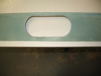
Then I took this puppy out back, clamped it to a sawhorse and routered a 1/4″ radius on the access hole’s edge. I was going to try to go with the same style as the CS spar oval access hole as far as the hole’s edge, but I simply didn’t have enough clearance to work with. So, except for the straight bottom edge of the oval, I’ll cut a wedge out of the foam on the back edge and create an internal flox wedge to strengthen the glass at the hole’s edge.
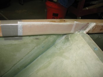
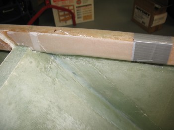
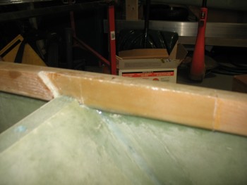
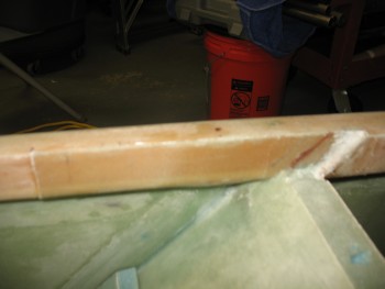
Sorry for the crappy pics below, but they show the cured 2-ply longeron layups that will add a base & some strength for the rollbar side rails. I specifically DIDN’T add glass to the tops of the longerons simply to avoid adding height to the side rails in order to minimize clearance issues with the canopy frame.
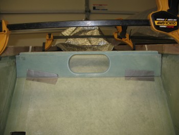
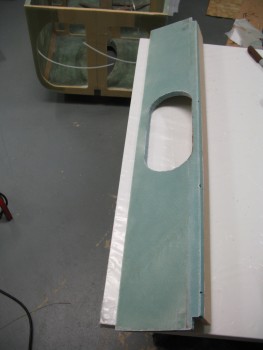
And here’s a shot with the lower seat back piece with the newly cut access hole thrown in place for a quick mock-up.
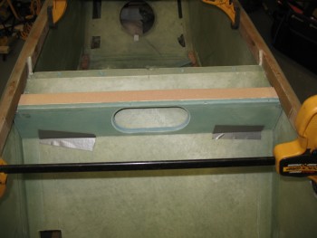
And a head on shot of the same.