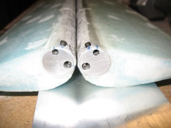
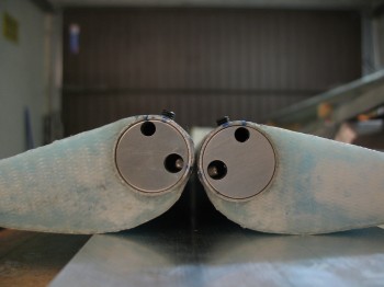
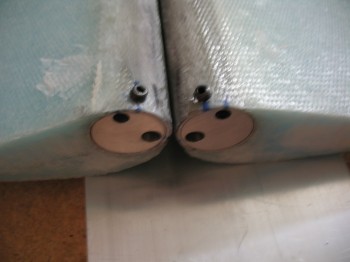
I started today by installing the elevator tube end inserts (NC-6) into the Outboard end of the elevators.
I lined up the stainless steel hinge pin, then marked & drilled a #10 hole for the setscrew. After the setscrew was in, I insured the NC-6 was even with the Outboard edge of the elevator tube & then drilled a #30 hole to set a PPC-42 Cherry Pop Rivet.
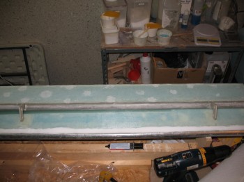
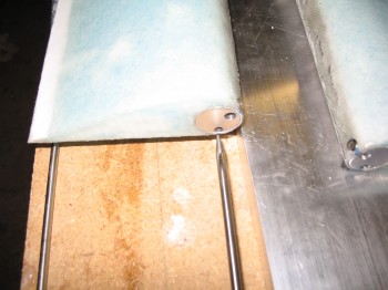
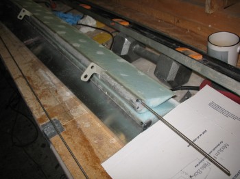
 In the picture below the stainless steel hinge pins are shown to Left of the elevators.
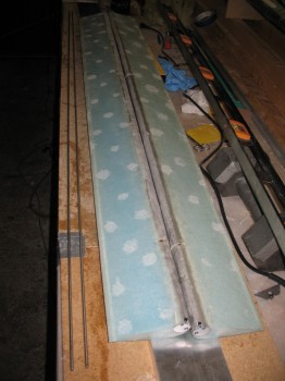 I gathered up all my NC-3 elevator hinges, 3 for each elevator.
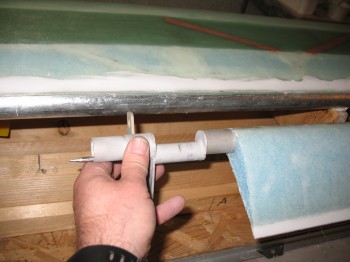
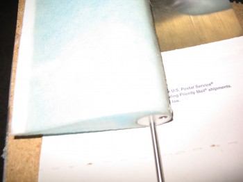
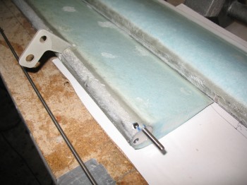
 I then installed the SS hinge pin starting on the Outboard side of each elevator at the NC-6 tube end insert . . . then through the two hinge inserts (NC-2) and ending up at the Inboard side of the elevator. [Note: Again, I’m installing the Cozy Girrrl’s elevator torque offsets (shown below), thus there are different amounts of elevator hardware required than spelled out in the Roncz Canard plans.]
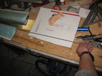
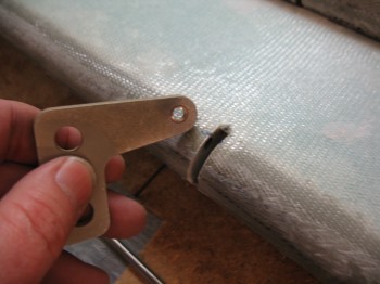
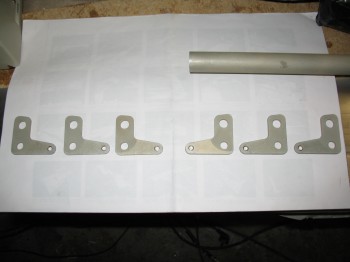
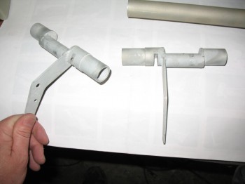
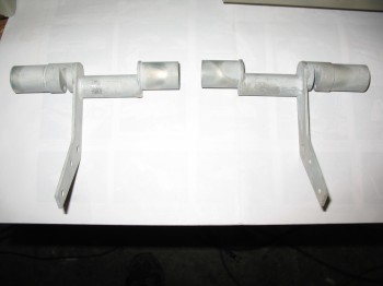 These pics show the Cozy Girrrl’s Elevator Torque Offsets. These have the smaller offset tube towards the middle of the assembly which provides a more concentric movement, and thus less removal of fuselage sidewall material is required for elevator travel (as compared to the stock plans configuration) as this assembly pivots when the elevator controls are moved. Obviously significantly less material removed and not having to have a decent-sized slot on each side of the fuselage greatly mitigates the amount of air (usually reported as “cold”) that sneaks into the cockpit.
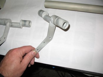
Now back to inserting the hinge pin . . . note the hinge pin hole in the torque offset that I’m holding in my hand in the pic above.
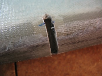
 So, the hinge pin insertion exercise went fine on the Right elevator . . . However, the Left elevator decided to be a PITA & not be so cooperative. It was as if some invisible force was blocking the hinge pin from going through the first hinge insert (NC-2). I tried everything I could think of . . . then I realized something was blocking it, the bottom of the hinge insert trough that the hinge (NC-3) was supposed to slide into. It wasn’t a clearance issue laterally left-to-right with the hinge pin, it was an up-n-down issue with the hinge not having clearance at the bottom of the hinge insert to be inserted far enough.
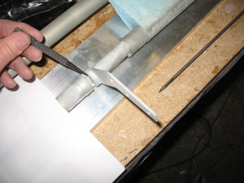
After messing around with it for another 1/2-hour or so, I grabbed my square file and filed the bottom of the NC-2 hinge insert trough. Slowly but surely, that did the trick. I’m not sure how or why this happened, but I needed to file down about 0.05″ to get the hinge “top” to freely pivot in the hinge slot.
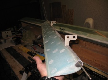
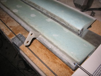
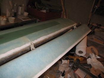
Once I got that issue out of the way, I mocked up the hinges to their dense foam mounts on the canard.
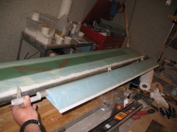
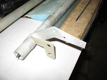
 In the pic below the Inboard hinge/torque offset looks drastically off from its associated dense foam mounting point on the canard. The reason why is that the torque offset actually gets mounted much farther Outboard (in relation to the elevator itself, not the canard) than what I have mocked up in the pic. There’s quite a few inches of the Inboard elevator tube–along with some glass & foam as well–that gets removed to make this happen.