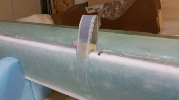
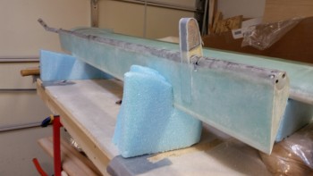
I started today by laying up the 11″ long 2-Ply strip of UNI around the outboard weight on the right elevator. I peel plied it and moved on to the other elevator.
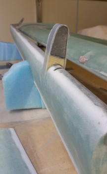
Just as I did on the right side elevator, I shaped the 6# yellow foam and floxed the outboard elevator weight setup to the front of the left elevator.
While the flox was curing on the left-side outboard elevator weight assembly, I double-checked a few plans items and also drilled and mounted the right side INBOARD lead weight. I also predrilled the first hole on the left side INBOARD elevator weight as well.
Not shown is some work I did on the inboard rib of the right wing to mount two click bonds for the aileron hinge bearing assembly. After floxing the click bonds into place, I laid up 2 plies of BID over the click bonds, added a taped-up washer over each click bond and screwed them down to ensure a flat surface for mounting the aileron hinge bearing. I should have a pic of this tomorrow.
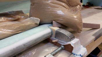
By the time I finished some miscellaneous tasks, the flox on the left elevator outboard weight had cured enough where I could layup the 11″ long 2-Ply strip of UNI around the weight/foam arm.
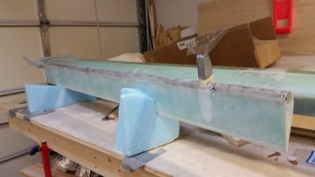
If you look closely, the only real difference between the pics below is that the INBOARD elevator weight is mounted in the bottom pic.
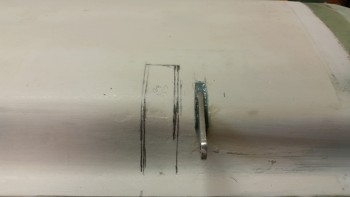
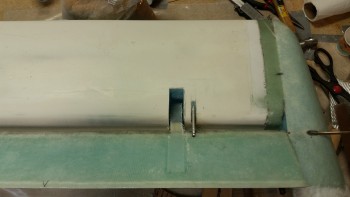
A few hours later I mocked up the elevators and made the embedded notch in the canard on the left side to allow clearance for the outboard elevator weight.
And here’s the left elevator with attached outboard weight moving freely in/out of the notch on the canard.
Next, I’ll be finishing up the notch on the right side of the canard, glassing them and cleaning up the outboard elevator weight layups.

